

Negative electrode and lithium ion secondary battery
a secondary battery and negative electrode technology, applied in the field of negative electrode and lithium ion secondary batteries, can solve the problems of increasing the amount of electric power consumption power consumption, and multi-functionality of small electronic devices, and achieves high capacity and energy density, high quality current collection performance, and significant reduction of deformation and separation of active material layers.
- Summary
- Abstract
- Description
- Claims
- Application Information
AI Technical Summary
Benefits of technology
Problems solved by technology
Method used
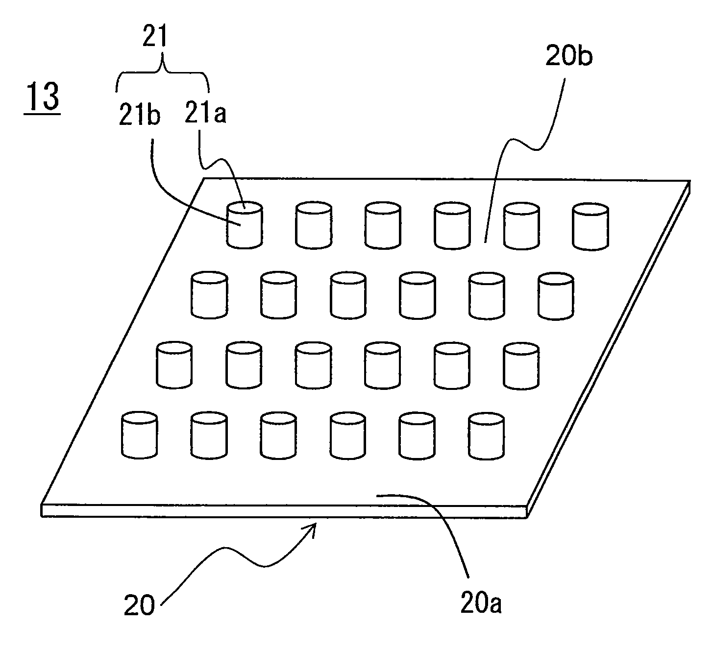
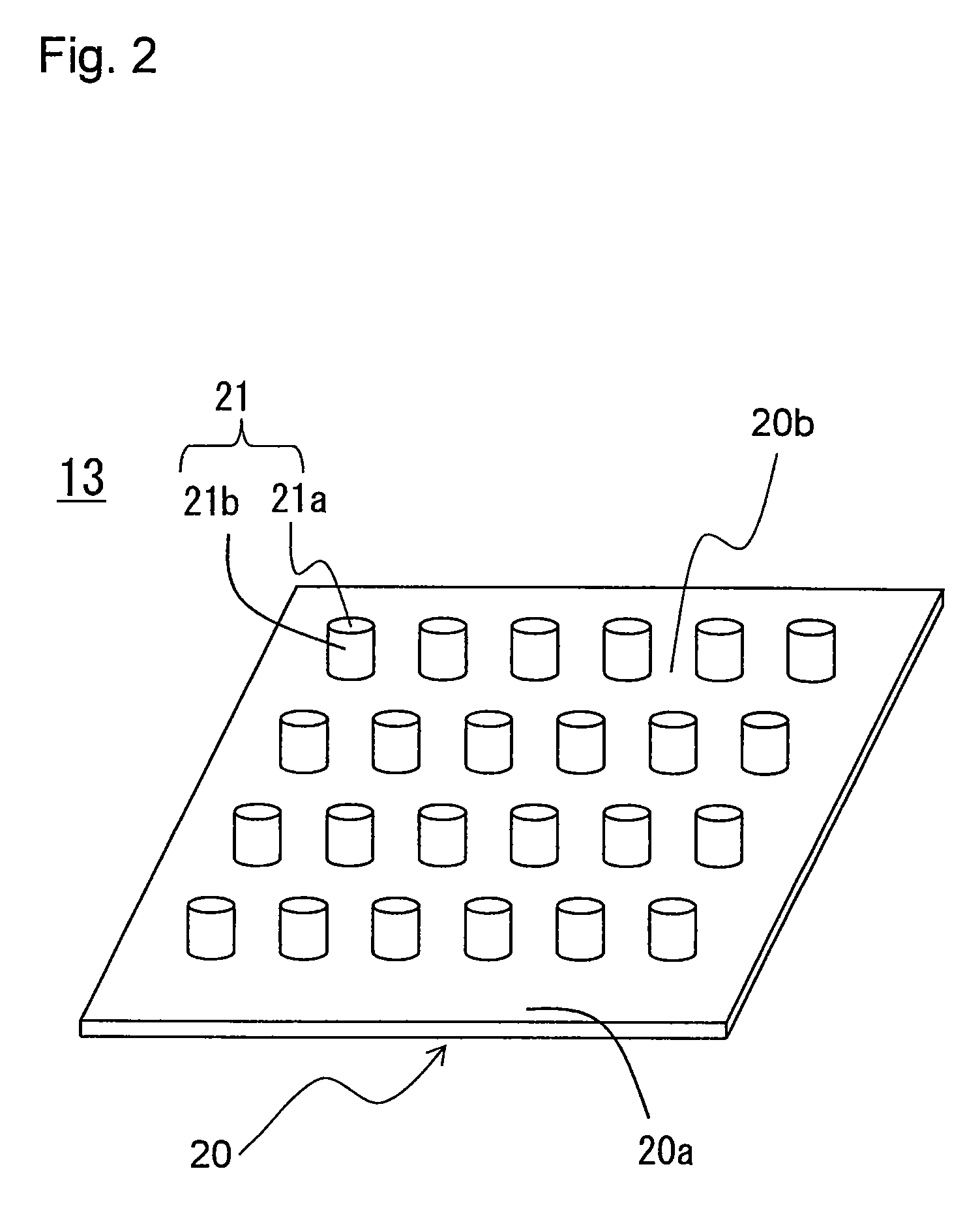
Image

Examples
example 1
(1) Positive Electrode Active Material Preparation
[0115]Cobalt sulfate and aluminum sulfate were added to an aqueous solution of NiSO4 such that Ni:Co:Al=7:2:1 (molar ratio) was satisfied, thereby preparing an aqueous solution having a metal ion concentration of 2 mol / L. To this aqueous solution, a 2 mol / L sodium hydroxide solution was dropped gradually while stirring to neutralize, thereby producing, by co-precipitation, a ternary precipitate having a composition represented by Ni0.7Co0.2Al0.1(OH)2. This precipitate was separated by filtration, washed with water, and dried at 80° C., thereby obtaining a composite hydroxide. As a result of measuring the average particle size of the obtained composite hydroxide with a particle size distribution meter (product name: MT 3000, manufactured by Nikkiso Co., Ltd.), it was found that the average particle size was 10 μm.
[0116]This composite hydroxide was heated in air at 900° C. for 10 hours, thereby obtaining a ternary composite oxide havin...
PUM
| Property | Measurement | Unit |
|---|---|---|
| diameter | aaaaa | aaaaa |
| height | aaaaa | aaaaa |
| surface roughness Ra | aaaaa | aaaaa |
Abstract
Description
Claims
Application Information