Management system for drilling rig power supply and storage system

a management system and power supply technology, applied in non-electric variable control, process and machine control, instruments, etc., can solve the problems of increasing the overall rig fuel consumption rate, increasing the cost of operation, so as to reduce the number of operating gensets, increase the demand for generators, and improve the effect of efficiency

Inactive Publication Date: 2009-12-17
INR G LINKS
View PDF33 Cites 88 Cited by
  • Summary
  • Abstract
  • Description
  • Claims
  • Application Information

AI Technical Summary

Benefits of technology

[0020]It is an important feature of the invention that the system provided herein permits the reduction of the number of operating gensets on the rig. In practice, rigs have different numbers of generators typically 2 to 6. In some cases, less than all generators are in simultaneous operation. In other cases all generators may be run. This may be needed in periods of peak demand when the battery is at a low state of charge. That is, the present invention may actually increase the demand on the generators rather than reduce it. Specifically, the configurations of the present invention permit the generators to run at a higher state of efficiency. This is because the need for over capacity is reduced or eliminated by the peak shaving function of the power conditioner and energy storage device. Excess power is stored in the energy storage device during periods of off-peak demand and then used during periods of peak demand. Generators can then be started and stopped over longer time intervals to provide the average power requirement of the rig and the state of charge of the energy storage device.
[0021]In the past, the additional capacity was needed and had to be continuously operating because of the lag time in bringing up an additional genset from a dormant or an off condition. The storage / source system of the subject invention provides additional power on demand, eliminating the need to have ready reserve generating capacity. This not only provides a consistent source of power on demand but eliminates the costs associated with supplying and supporting the additional genset and the associated increase in fuel required to operate the same. With this feature, the additional costs of incorporating the system of the subject invention in a rig power supply is greatly neutralized by the cost savings associated with the reduction in the number of operating gensets. By way of example, if two gensets are operating at 40% using prior art systems versus one genset operating at 80% using the configuration of the subject invention, the fuel usage is much higher because the generator efficiency decreases at lower loading. Typically, 80% load is near optimum efficiency.
[0022]Overall engine generators maintenance cost will be reduced by the use of invention. Typical engine generator service and maintenance costs are in the $2-4 per hour for each engine generator. This made up of oil consumption, oil and filter changes, AC generator overhaul, engine top jobs and major overhaul costs. Due to the engines generator system being run at higher average loads and in a more efficient manner the overall the result will be a significant reduction in the over all cost ownership of the rig engine generator package. In addition, the fact that much of the time you will be running one less engine generator than normal will provide even more significant savings.

Problems solved by technology

This has resulted in a significant increase in the overall rig fuel consumption rate.
Over the last few decades, SCR and VFD rigs have become much more common and DC / DC and mechanical rigs are becoming scarce.
Typical operation of the rig results in a highly dynamic power consumption profile that leads to inefficiency.
Specifically, the rig power source has to be prepared to provide maximum power on demand and this means that during periods of low power consumption the rig power source is producing or has the capacity to produce more power than is required, making the operation inefficient.
In addition, the typical rig is configured to operate in a failsafe manner such that failure of a portion of the gensets will not shut down the rig or prevent a critical operation from taking place requiring instantaneous incremental rig power from the generators online.
This is critical because anytime a rig operation is shut down it is possible that the well will be lost.
At a minimum, hours to days of drilling time may be lost.
The typical genset configuration results in power factor inefficiencies which are roughly equal to the ratio of the actual output to the full voltage output capability.
This results in higher fuel consumption by running the engine (typically a diesel engine) at a lower than optimum efficiency.
In addition, many of the operational motors such as the mud pumps typically operate at high pressure (and high current) and speeds lower than rated.
Also, during periods of transient loads, it is not possible for the generation of power from the gensets to match the dynamic load of the operational equipment and dramatic power factor inefficiencies occur during the period required by the gensets to compensate for the changing load.
Without such contingencies any shut down of the rig or lack of instantaneous incremental power can result in costly or potentially catastrophic consequences.
This solution was obviously not effective on single motor mud pumps, or when as commonly occurred, pumps had to be run at a greater than 50% speed to produce the required volume.
At low loads, the corrected power factor could be as poor leading as a result of the added KVAR as it was lagging without the compensation by the capacitors.
Because the available power factor compensation was voltage dependent, and an increased KVAR demand (low voltage) was not met by an increased capability to compensate the power factor, voltage regulation was adversely affected.
Furthermore, system short circuit current was significantly increased, often beyond the original rig design limits, and the introduction of capacitance gave the system both sub-synchronous and super-synchronous resonant frequencies not easily calculated but within the range of excitation by the SCR drive system, thereby creating potential system stability problems.3. The rig generators were oversized, such that it was not uncommon to find 1500 KVA generators on 850 KW engines.
Even this solution was not often sufficient and was expensive when done for all engine-generator sets.
Aside from the higher initial capital expense required to provide oversize generators, the operation of oversized lightly loaded generators was inherently inefficient.4. A power factor controller was provided for AD / DC drilling rigs and utilized a controlled, unloaded, over-excited generator to provide reactive power to maintain the rig power factor within acceptable limits during peak demand operations, see for example, U.S. Pat. No. 4,590,416, entitled: “CLOSED LOOP POWER FACTOR CONTROL FOR POWER SUPPLY SYSTEMS,” issued to Michael N. Porche, et al, on May 20, 1986.
While each of these approaches worked toward assuring the availability of power during peak periods, each was deficient in that it either did not greatly reduce the inefficiency of the system or was inherently unstable.
Both conditions are detrimental to the safe and efficient operation of the rig.

Method used


Image

  • Management system for drilling rig power supply and storage system
  • Management system for drilling rig power supply and storage system
  • Management system for drilling rig power supply and storage system

Examples


Embodiment Construction

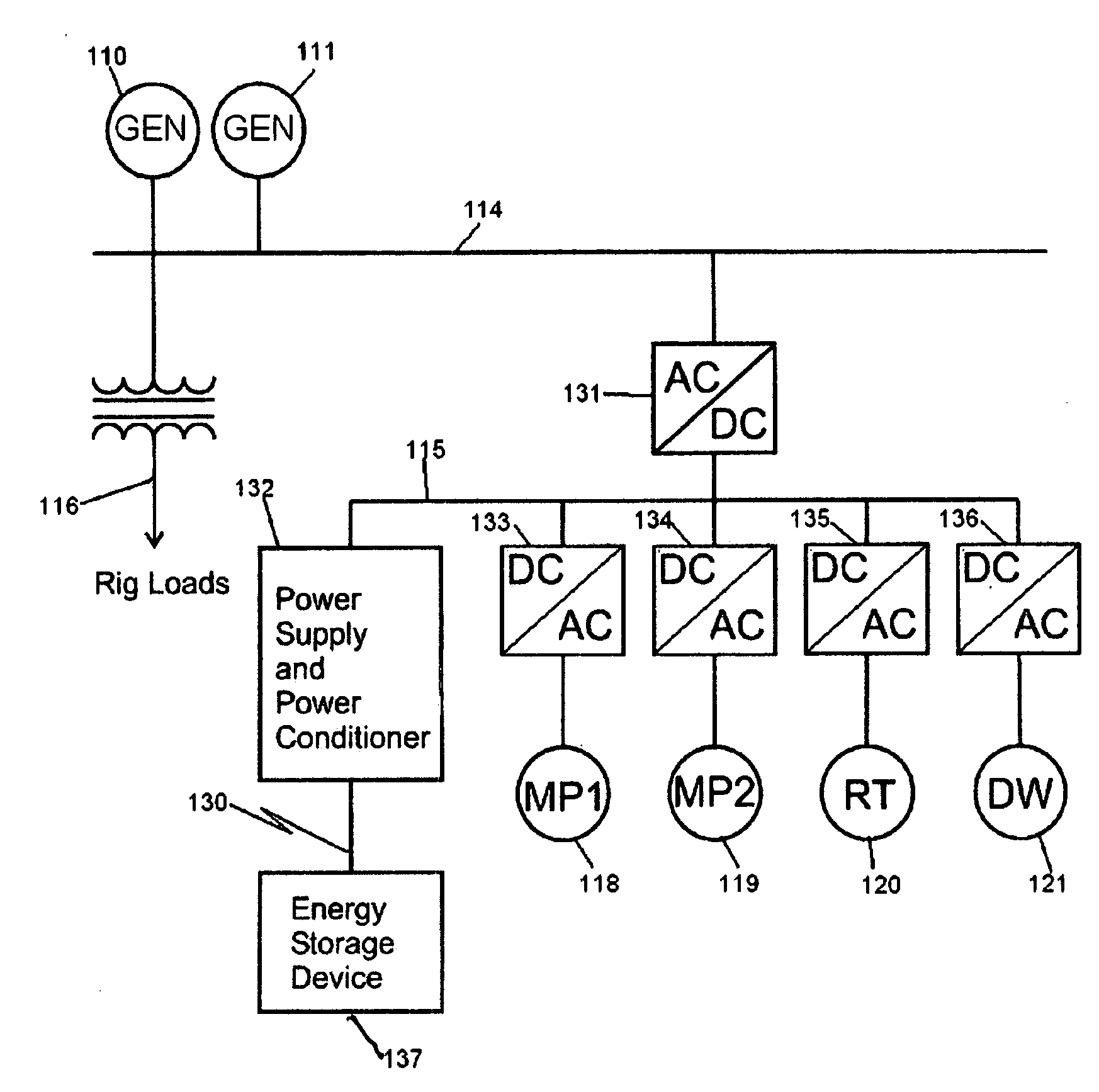
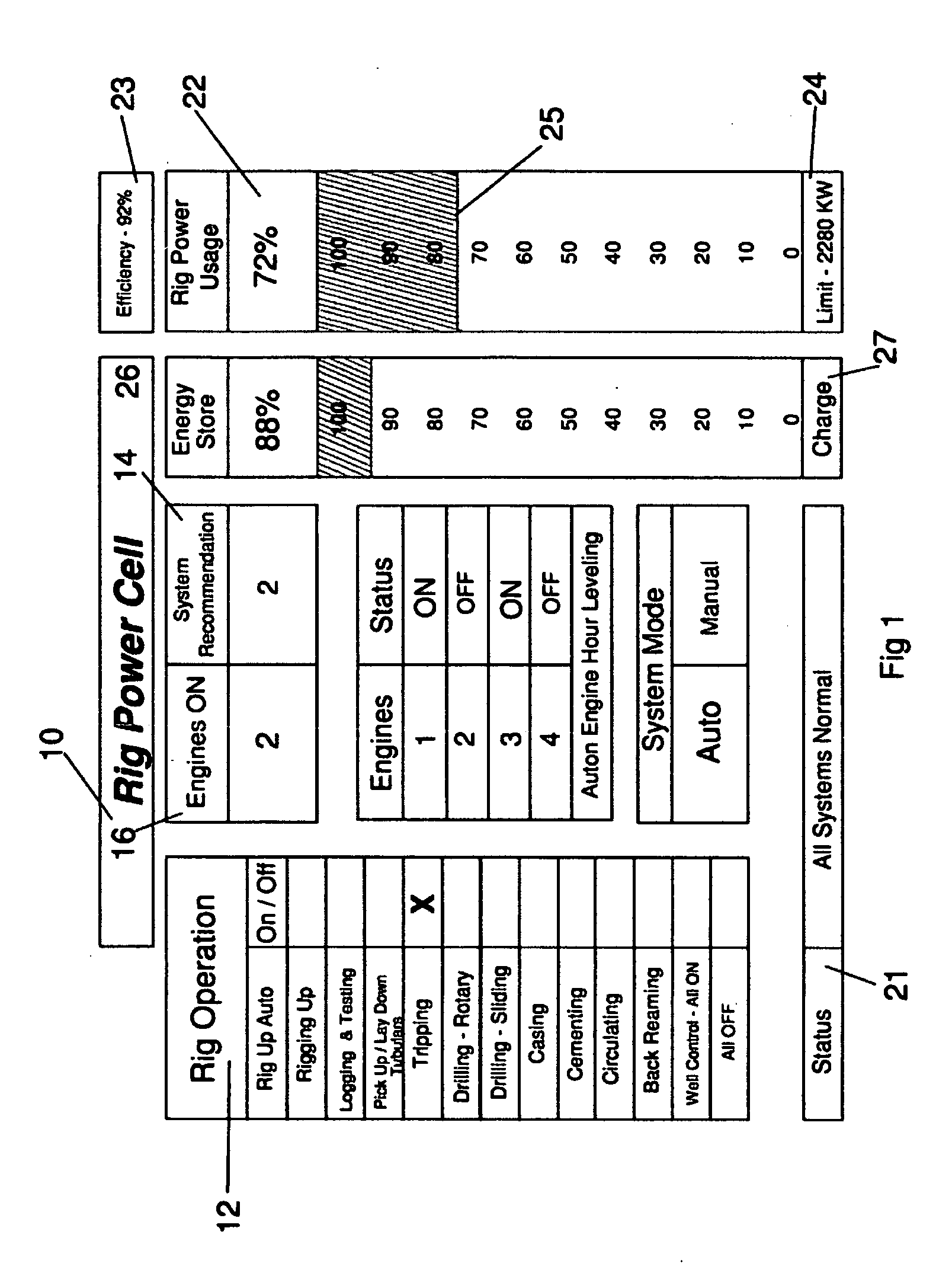
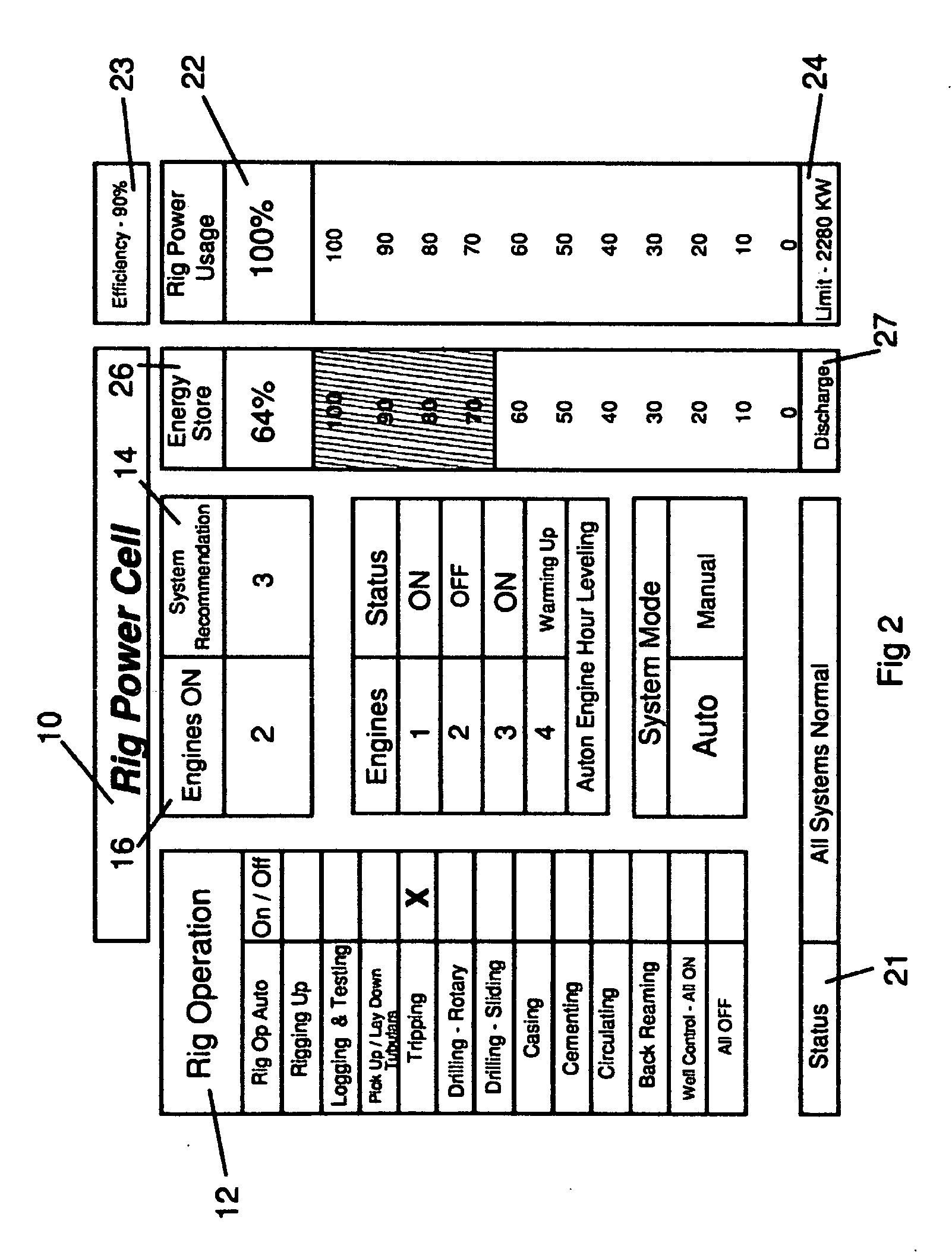
[0032]The subject invention comprises a method for managing an energy supply and storage system for a rig power supply of the type having a power generator coupled to rig loads, the power generator used for powering the rig and for charging the storage system, and the storage system adapted for selectively supplementing rig power, the method comprising the steps of: selecting a rig function operation; setting the system to recommended settings for the selected rig function operation; monitoring rig power usage for the selected rig function operation; distributing excess power to the storage system when the rig power usage falls below a preselected threshold; and distributing stored power from the storage system when the rig power usage is above a preselected threshold. In the preferred embodiment the recommended setting for the selected rig function may be modified depending upon power usage by setting preselected thresholds.

[0033]Typically, the rig includes a plurality of engines f...


PUM


Abstract

Management control system for managing an energy supply and storage system for a rig power supply of the type having a power generator coupled to rig loads, the power generator used for powering the rig and for charging the storage system, and the storage system adapted for selectively supplementing rig power, is adapted for controlling the selection of rig function operation, for setting the system to recommended settings for the selected rig function operation, for monitoring rig power usage for the selected rig function operation for distributing excess power to the storage system when the rig power usage falls below a preselected threshold, and for distributing stored power from the storage system when the rig power usage is above a preselected threshold. The recommended setting for the selected rig function may be modified depending upon power usage by setting preselected thresholds.

Description

BACKGROUND OF THE INVENTION[0001]1. Field of the Invention[0002]The present invention is generally related to a management system for power supplies for drilling rigs and is specifically directed to an apparatus and a method for managing the conversion of chemical energy to electrical energy and for improving the energy efficiency of the rig through management of regeneration and improved power factors.[0003]2. Description of the Prior Art[0004]In the petroleum exploration industry the equipment used to bore wells for oil and gas recovery is commonly known as a drilling rig. Over the years, various types of rigs have been used by the industry and have been classified either by reference to the type of power used on board the rig to provide the motive force necessary to turn the drill bit or perform the other rig operations or as to the type of terrain on which the rig is situated. For example, a rig may be termed an “offshore” rig if it is one used for offshore drilling, but more co...

Claims


Application Information

Patent Timeline
Patent Type & Authority Applications(United States)
IPC IPC(8): G06F1/28H02J4/00
CPCH02J3/38H02J3/32
Inventor BUIEL, EDWARD R.
Owner INR G LINKS
Why Eureka
Try Eureka