Membrane-Based Assay Devices that Utilize Time-Resolved Fluorescence

a technology of membrane-based assay and time-resolved fluorescence, which is applied in the direction of fluorescence/phosphorescence, analysis by material excitation, instruments, etc., can solve the problems of reducing detection accuracy, unable to integrate time-resolved techniques in other types, and exist with conventional fluorescent detection techniques, etc., to achieve accurate excitation labels

Inactive Publication Date: 2009-12-24
KIMBERLY-CLARK WORLDWIDE INC
View PDF3 Cites 26 Cited by
  • Summary
  • Abstract
  • Description
  • Claims
  • Application Information

AI Technical Summary

Benefits of technology

[0015]The fluorescent reader can be used to accurately excite labels and detect fluorescence on a membrane-based assay device without requiring the use of expensive components, such as monochromators or narrow emission bandwidth optical filters. In one embodiment, for example, the pulsed excitation source is a silicon photodiode. The fluorescence reader may also contain timing circuitry (e.g., A / D convertors, microprocessors, amplifiers, dividers, crystal oscillators, transistors, flip-flop circuits, etc.) in communication with the pulsed excitation source and the time-gated detector to control signal pulsation and detection.

Problems solved by technology

However, several problems exist with conventional fluorescent detection techniques.
For instance, most biological fluids possess autofluorescence that can decrease detection accuracy.
Although “time-resolved” techniques have been successfully employed in some types of assay devices, such as cuvette-based instruments, problems nevertheless remain in incorporating time-resolved techniques in other types of assay devices, such as membrane-based devices.
In particular, conventional time-resolved systems, such as those based on monochromators, involve very complex and expensive instruments.
This level of complexity drastically increases the costs of the system and also requires a bulky, non-portable, and heavy instrument.
In addition, conventional time-resolved systems are also problematic when used in conjunction with membrane-based assay devices.
Unfortunately, background interference becomes increasingly problematic at such low analyte concentrations because the fluorescent intensity to be detected is relatively low.

Method used


Image

  • Membrane-Based Assay Devices that Utilize Time-Resolved Fluorescence
  • Membrane-Based Assay Devices that Utilize Time-Resolved Fluorescence
  • Membrane-Based Assay Devices that Utilize Time-Resolved Fluorescence

Examples


example 1

[0075]The ability to form conjugated fluorescent probe particles for use in a membrane-based device was demonstrated. 500 microliters of 0.5% carboxylated europium chelate encapsulated particles (0.20 microns, EU-P particles, obtained from Molecular Probes, Inc.) were washed with 100 microliters of a PBS buffer (0.1 molar). 40 microliters of the washed particles were then applied with 3 milligrams of carbodiimide (from Polysciences, Inc.). The mixture was allowed to react at room temperature (RT) for 30 minutes on a shaker. The activated particles were then washed twice with a borate buffer through centrifugation. The activated particles were again re-suspended in 200 microliters of a borate buffer through a 2-minute bath sonication.

[0076]Thereafter, 30 microliters of C-reactive protein (CRP) (4.9 milligrams per milliliter, Mab1 A58110228P, obtained from BiosPacific, Inc. of Emeryville, Calif., was added to the activated particles. The reaction mixture was allowed to react at room t...

example 2

[0077]The excitation and emission spectra of the conjugated probe particles formed in Example 1 was determined using a conventional FluoroLog III spectrofluorometer (purchased from Horiba Group) using an excitation wavelength of 370 nanometers and an emission wavelength of 615 nanometers.

[0078]The results are shown in FIG. 5. As shown, the excitation and emission spectra of the probe particles were similar to the excitation and emission spectra of the unconjugated probe particles, except the relative intensity of the 430 nanometer peak to 615 nanometer peak for the conjugate was higher. The conjugated probe particles had a strong excitation peak at around 355 nanometers and two strong emission peaks at 430 and 615 nanometers. The emission peak at 430 nanometers was believed to originate from the ligand while the peak at 615 nanometers was believed to be from d-d transition of europium metal ion through energy transfer from ligand to the europium metal center.

example 3

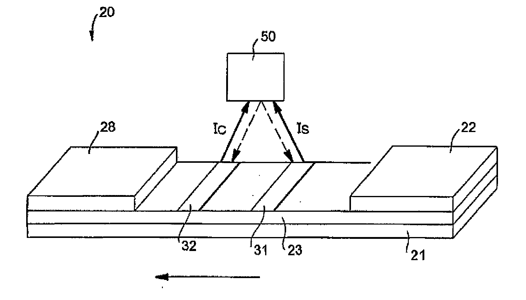
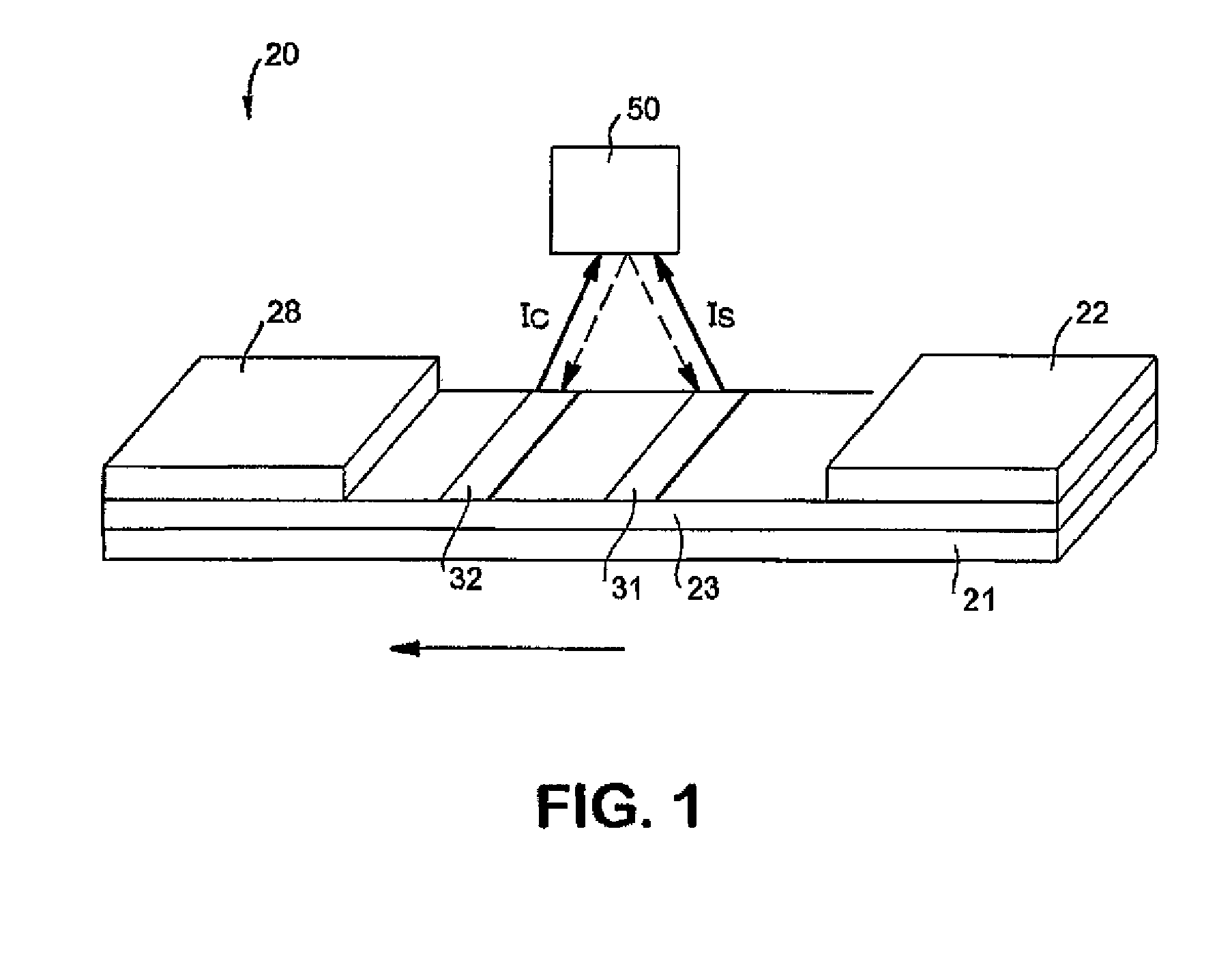
[0079]The ability to form a membrane-based assay was demonstrated. Initially, Millipore SX porous membrane samples made of nitrocellulose were laminated onto corresponding supporting cards having a length of approximately 30 centimeters. C-reactive protein (CRP) monoclonal antibody (Mab A58040136P, 2.3 mg / ml, obtained from BiosPacific, Inc. of Emeryville, Calif.) was striped onto the membrane to form a detection line. Goldline (a polylysine solution obtained from British Biocell International) was then striped onto the membrane to form a calibration line. The membrane was dried for 1 hour at 37° C.

[0080]A cellulosic fiber wicking pad (Millpore Co.) was attached to one end of the membrane. The other end of the membrane was laminated with two glass fiber pads (sample and conjugate pads) obtained from Millipore Co. The conjugate pad and wicking pad were in direct contact with the membrane, and the sample pad was in direct contact with the conjugate pad. The conjugate pad and sample pad...


PUM

PropertyMeasurementUnit
timeaaaaaaaaaa
Timeaaaaaaaaaa
fluorescence lifetimeaaaaaaaaaa

Abstract

A membrane-based assay device for detecting the presence or quantity of an analyte residing in a test sample is provided. The device utilizes time-resolved fluorescence to detect the signals generated by excited fluorescent labels. Because the labels can have relatively long emission lifetime, short-lived background interference can be practically eliminated through delayed fluorescence detection. In addition, the resulting fluorescent reader can have a simple and inexpensive design. For instance, in one embodiment, the reader can utilize a silicon photodiode and a pulsed light-emitting diode (LED) to accurately excite labels and detect fluorescence on a membrane-based assay device without requiring the use of expensive components, such as monochromators or narrow emission band width optical filters.

Description

RELATED APPLICATIONS[0001]The present application is a continuation of U.S. application Ser. No. 10 / 286,342, filed on Nov. 1, 2002.BACKGROUND OF THE INVENTION[0002]Assays have been developed that employ fluorescent labels to facilitate detection of the analyte. Fluorescence is generally the result of a three-stage process. In the first stage, energy is supplied by an external source, such as an incandescent lamp or a laser, and absorbed by the fluorescent compound, creating an excited electronic singlet state. In the second stage, the excited state exists for a finite time during which the fluorescent compound undergoes conformational changes and is also subject to a multitude of possible interactions with its molecular environment. During this time, the energy of the excited state is partially dissipated, yielding a relaxed state from which fluorescence emission originates. The third stage is the fluorescence emission stage wherein energy is emitted, returning the fluorescent compo...

Claims


Application Information

Patent Timeline
Patent Type & Authority Applications(United States)
IPC IPC(8): G01N21/64G01T1/20
CPCG01N21/274G01N21/6408G01N21/6428G01N33/525G01N33/533G01N2201/0696G01N33/558G01N33/582G01N2021/6439G01N2201/062G01N33/542G01N33/54388
Inventor SONG, XUEDONGKAYLOR, ROSANNKNOTTS, MICHAELWEI, NING
Owner KIMBERLY-CLARK WORLDWIDE INC
Why Eureka
Try Eureka