Slurries (mixtures of liquids and solid particles) are more difficult to pump than particle-free fluids.
The presence of solid particles adversely affects pump efficiencies and valve lifetimes, especially at high pressures and / or high flow rates.
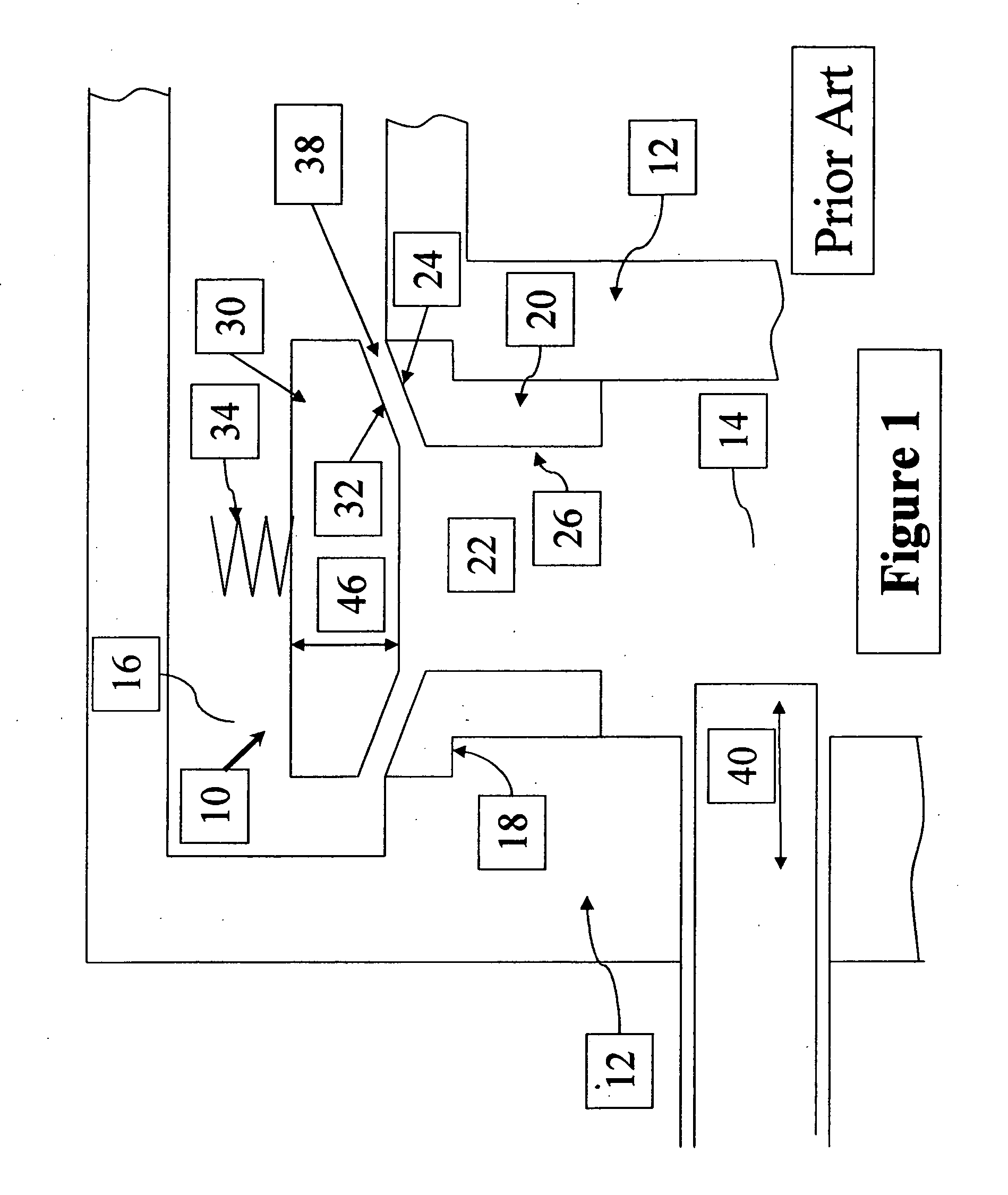
However, when the forward motion of the
plunger slows and the valve begins to close, solid particles in the fluid can become trapped within the valve
assembly.
The trapped solids prevent the valve from fully closing and thereby reduce the efficiency of the pump.
Trapped solids can also damage the valve
assembly components and reduce the useful life of the valve
assembly.
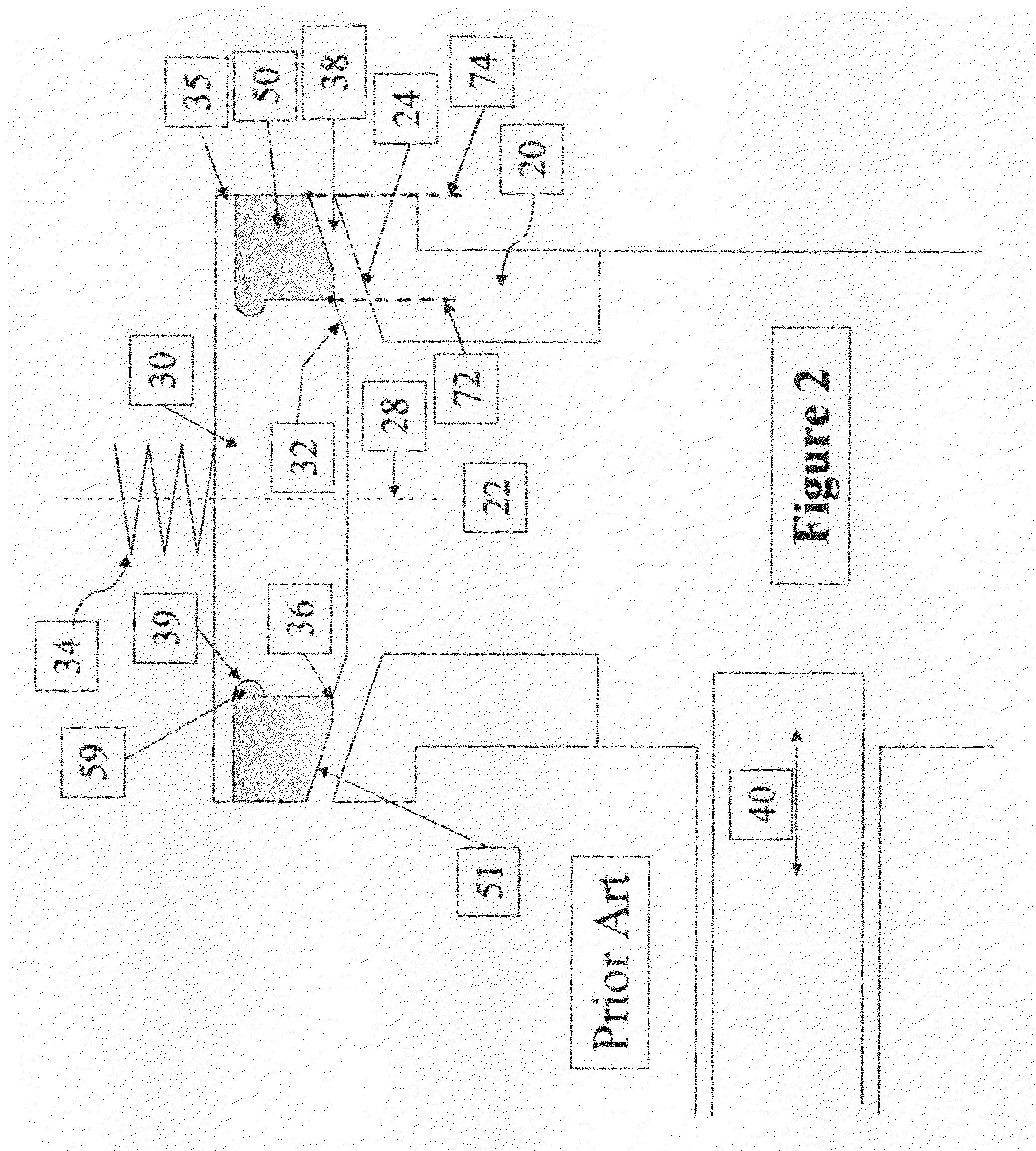
The valve lifetime can be quite long and may even outlast the fluid end of the pump in endurance test runs when the pumping medium is a clear fluid.
However, when the pumping medium is a
slurry, such as a
fracturing fluid with proppant, the
metal contact surfaces in the strike face area are severely damaged by
erosion, abrasion and by pitting caused by solid particles in the fluid.
The damage caused by trapped particles is extensive.
While useful, this technique has not been wholly successful.
Damage to the
metal surfaces near to and along that perimeter increases the
extrusion gap size that the resilient insert has to span in order to form an effective
hydraulic seal.
This creates concentrated stress forces at these locations and leads to localized pitting.
This greatly accelerates the damage at these locations.
Repeated deformation of the insert material causes internal heat build-up and material stress within the insert material, and this can damage it.
The insert material has low
thermal conductivity, and even when bathed in flowing fluid the insert can overheat and be permanently deformed if exposed to large percentage deformations of the insert material.
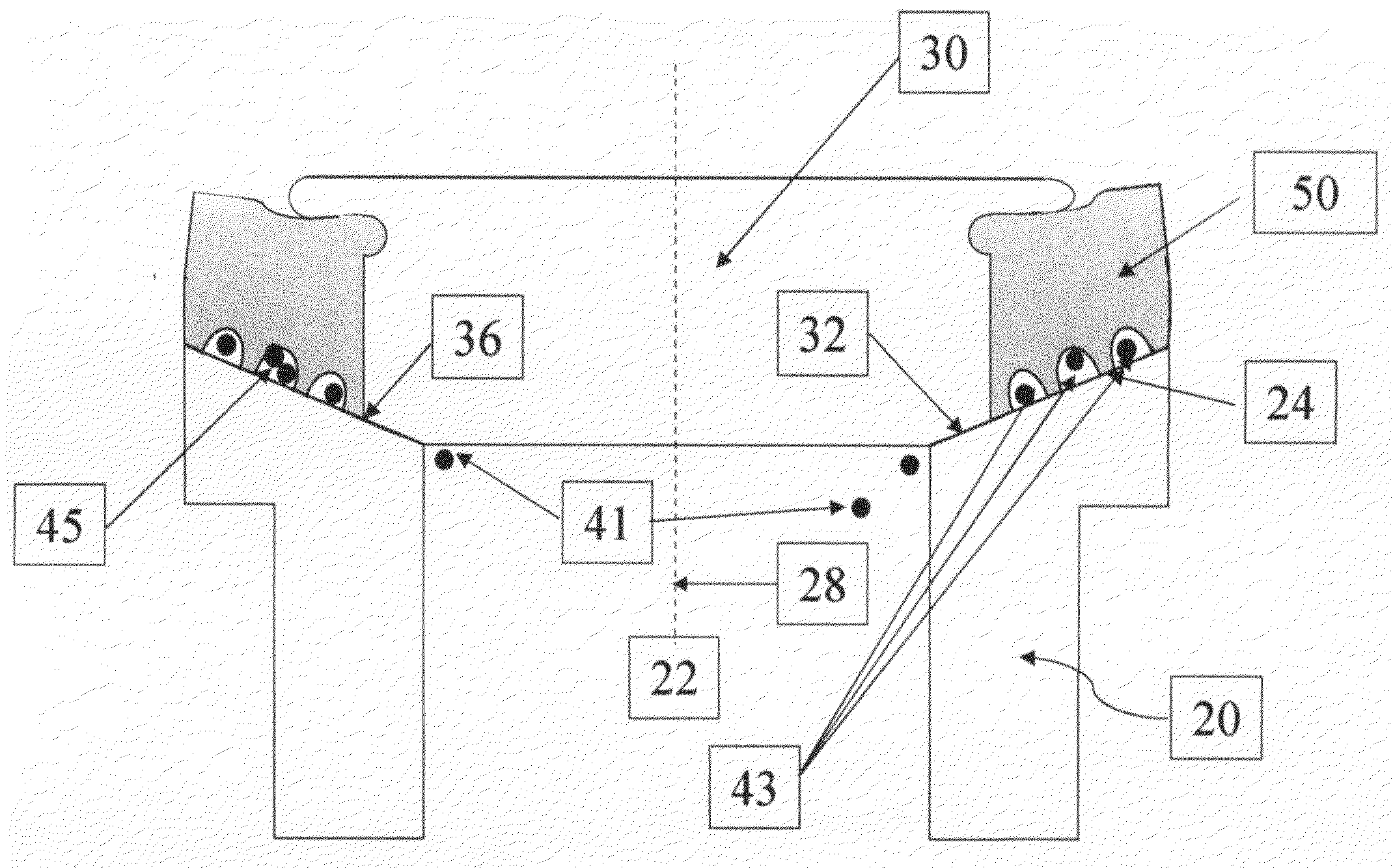
Damage to the valve insert is also caused by large deformations of the insert material beyond its elastic limit.
In the presence of proppant, the
metal surfaces of the valve closure member and valve seat member do not form a good
hydraulic seal.
Such concentrations of proppant particles enhance damage to the contacting surfaces of the valve closure member and the valve seat member.
However, the volume of fluid without proppant, which flows through current valves during the short time interval between the onset of such reverse particle screening and the closure of the valve, typically is insufficient to displace the proppant-laden fluid from the valve before closure.
Larger offsets would result in larger insert material deformations leading to heating and material failure.
That increases heating and deformation damage to the insert member.
Additional deformation damage to the resilient insert member is caused by
trapping proppant particles between the resilient insert member and the valve seat member when the valve is closed.
Larger proppant particles will cause significantly increased deformation damage and
embedment damage when trapped between the resilient insert member and the valve seat member when the valve closes.
Another problem with conventional valves for high-pressure
slurry pumps, such as the reciprocating
plunger pumps mentioned above, is the
impact of the valve closure member on the valve seat member when the valve exhibits valve
lag, closing after the pump
plunger has reversed direction.
However, large amounts of valve
lag lead to damage of conventional valves, as the valve closure member slams into the valve seat member with
high velocity and considerable force in closing.

