Slab type laser apparatus

a laser apparatus and laser beam technology, applied in the field of laser beam apparatus, can solve the problem of large installation area, achieve the effect of suppressing the expansion of the beam, reducing the installation area, and maximizing the beam amplitud

Active Publication Date: 2009-12-24
GIGAPHOTON +1
View PDF3 Cites 37 Cited by
  • Summary
  • Abstract
  • Description
  • Claims
  • Application Information

AI Technical Summary

Benefits of technology

[0020]According to the present invention, since a driver laser is formed by using a slab type laser amplifier part as mentioned above, it is possible to downsize the driver laser, to amplify a laser beam efficiently, and to obtain a laser beam having a superior focusing performance by suppressing expansion of the beam.
[0021]Consequently, it is possible to obtain a space saving and efficient EUV generator by utilizing the laser a...

Problems solved by technology

However, the master oscillator power amplifier type laser apparatus having the above-mentioned configuration has an issue that a la...

Method used


Image

  • Slab type laser apparatus
  • Slab type laser apparatus
  • Slab type laser apparatus

Examples


embodiment 1

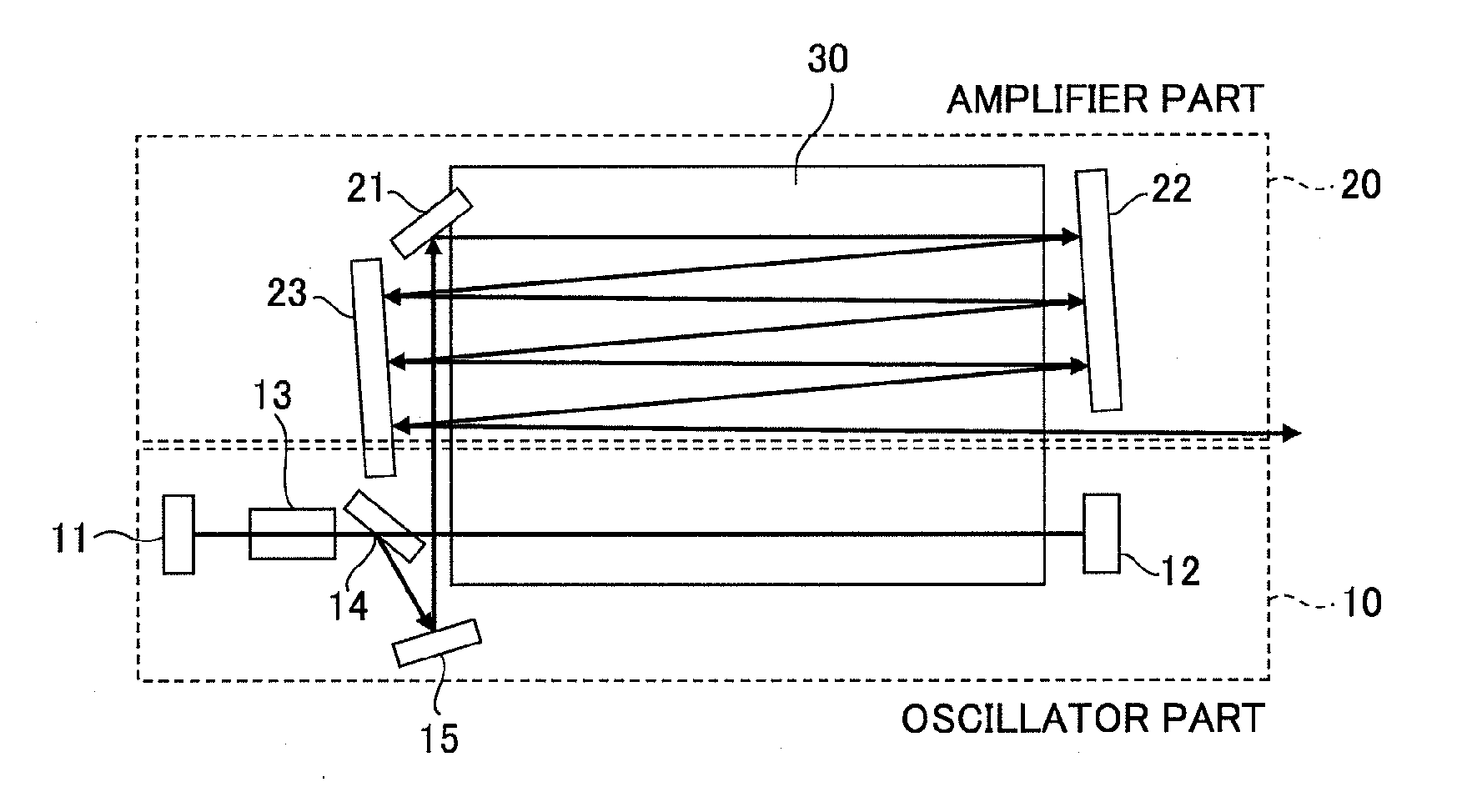
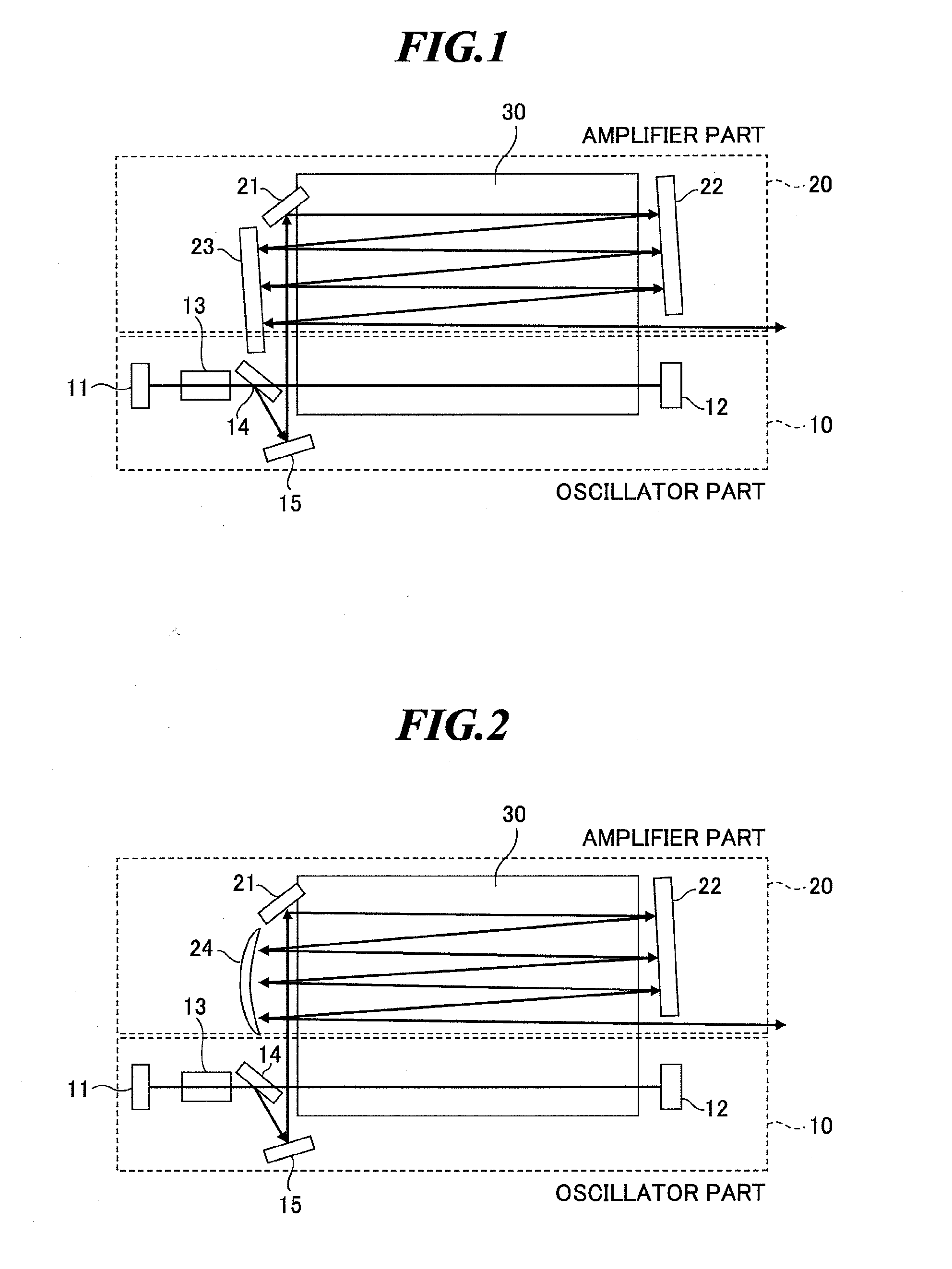
[0056]FIG. 1 is a schematic diagram showing a configuration of a slab type laser apparatus of a first example according to a first embodiment of the present invention.

[0057]A slab type laser apparatus according to this embodiment is a CO2 laser apparatus for supplying a laser beam to be applied to a target material to turn the target material into plasma in an extreme ultraviolet light source apparatus for supplying extreme ultraviolet (EUV) light to an exposure unit.

[0058]The slab type laser apparatus has a configuration in which an oscillator part 10 and an amplifier part 20 are integrated together with one body of a slab type CO2 laser medium part 30.

[0059]The CO2 laser medium part 30 forms a discharge field of slab type between a pair of electrodes in a region, in which the electrodes connected to a high-frequency power source (not shown) are disposed in opposition, by applying a high-frequency voltage to the electrodes to excite a CO2 laser medium containing a carbon dioxide ga...

embodiment 2

[0076]FIGS. 6-18 are drawings showing a slab type laser apparatus according to a second embodiment of the present invention. The slab type laser apparatus according to this embodiment is applied with an amplifier part having a stabilized optical axis by improving the optical system (return mirror optics) compared with the slab type laser apparatus according to the first embodiment, and has substantially the same configuration other than the amplifier part.

First Example

[0077]FIGS. 6 and 7 show a slab type laser apparatus of a first example according to the second embodiment. FIG. 6 is a schematic diagram showing a configuration concept of the slab type laser apparatus of the first example, and FIG. 7 is a side view showing a cross section of a part of the slab type laser apparatus of the first example.

[0078]As shown in FIGS. 6 and 7, the slab type laser apparatus of this example has the configuration in which the oscillator part 10 and the amplifier part 20 are integrated together wi...

fourth example

[0110]FIGS. 12 and 13 show a slab type laser apparatus of a fourth example according to the second embodiment of the present invention. FIG. 12 is a schematic diagram of an oscillator part and an amplifier part in the slab type laser apparatus of this example, and FIG. 13 is an optical system diagram regarding the amplifier part of this example.

[0111]The slab type laser apparatus of this example is a slab type laser apparatus of multi-path amplification type having substantially a similar configuration to the first example. The slab type laser apparatus of this example differs from the slab type laser apparatus of the first example in that an incidence mirror for taking a seed laser beam as an incident beam outputted from a polarizer in the oscillator part into an return mirror optical system directly from the side face of the amplifier part is provided by the side of a return mirror in the amplifier part, and that the laser beam goes and returns in a zigzag manner of multi-path in ...


PUM


Abstract

A slab type laser apparatus has a slab type gas laser medium part formed in a region defined by a pair of electrode flat plates oppositely disposed in parallel with each other in a space to be filled with a gas laser medium which is excited by high-frequency electric power. The apparatus includes an oscillator part including a pair of resonator mirrors oppositely disposed with a part of the gas laser medium part in between, and for amplifying a laser beam to have predetermined light intensity to emit the laser beam, and the amplifier part including a plurality of return mirrors oppositely disposed with a part of the gas laser medium part in between. The incident laser beam goes and returns plural times between the return mirrors, and the laser beam is amplified to have predetermined power.

Description

CROSS-REFERENCE TO RELATED APPLICATIONS[0001]The present application claims priority from Japanese Patent Applications No. 2008-154264 filed on Jun. 12, 2008 and No. 2009-029011 filed on Feb. 10, 2009, the content of which are herein incorporated by reference in their entirety.BACKGROUND OF THE INVENTION[0002]1. Field of the Invention[0003]The present invention relates to a slab type laser apparatus for emitting a pulse laser beam, and particularly to a slab type carbon dioxide gas (CO2) laser apparatus for emitting a driver laser beam to be applied to a target material to turn the target material into plasma for radiating extreme ultraviolet (EUV) light in an extreme ultraviolet light source apparatus.[0004]2. Description of a Related Art[0005]Recent years, as semiconductor processes become finer, photolithography has been making rapid progress to finer fabrication. In the next generation, micro-fabrication at 60 nm to 45 nm, further, micro-fabrication at 32 nm and beyond will be r...

Claims


Application Information

Patent Timeline
IPC IPC(8): H01S3/22H01S3/08
CPCG03F7/70025G03F7/70033H01S3/005H01S3/076H01S3/0971H01S3/115H01S5/4087H01S3/2316H01S3/2325H01S3/235H01S3/2375H01S5/141H01S3/2232
Inventor NOWAK, KRZYSZTOFSUGANUMA, TAKASHIWAKABAYASHI, OSAMUENDO, AKIRA
Owner GIGAPHOTON
Why Eureka
Try Eureka