Method for manufacturing porous body

Inactive Publication Date: 2009-12-24
LOTUS ALLOY
View PDF4 Cites 7 Cited by
  • Summary
  • Abstract
  • Description
  • Claims
  • Application Information

AI Technical Summary

Benefits of technology

[0011]The porous body production method of the present invention ensures excellent quality of the resulting porous body with control over porosity, pore size, pore form or the like, and the method can be performed even under atmospheric pressure, without requiring high pressure. According to the present invention, porous body production can be performed in a simpler

Problems solved by technology

However, because this method is incapable of controlling a gas bubble generation nuclei that is necessary for pore growth, the nuclei formation becomes uneven; therefore, the pores produced become uneven.
Moreover, since the gas is dissolved in a molten metal under pressure, this production method must be performed in a pressure vessel, which requires a complicated and

Method used


Image

  • Method for manufacturing porous body
  • Method for manufacturing porous body
  • Method for manufacturing porous body

Examples


embodiment 1

(i) Embodiment 1

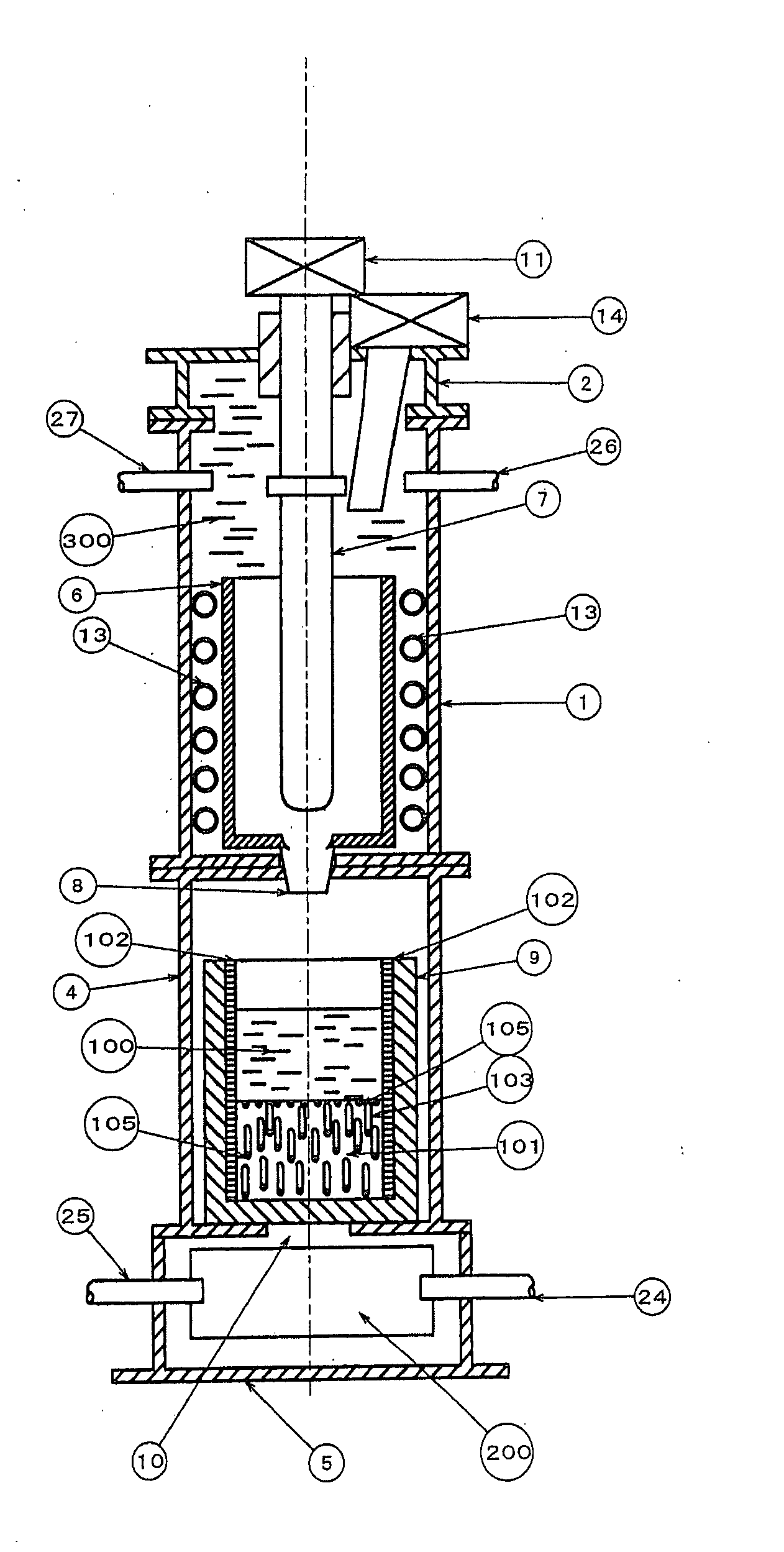
[0117]FIG. 1 is a cross-sectional view schematically showing an example of an apparatus for producing a porous body 101 used for the present invention. The apparatus of FIG. 1 includes a heating unit container 1 for heating and melting a porous body-forming material; and, vertically disposed, a solidification adjusting unit container 4 and a cooling unit container 5 for cooling and solidifying a molten raw material 100. The heating unit container 1 includes a crucible 6, a crucible stopper 7, an induction heating coil 13, a gas inlet 26, a gas outlet 27, and a funnel 8. Placed above the heating unit container 1 are a container cover 2, and a driving unit 11 for pulling up the crucible stopper 7.

[0118]First, the crucible stopper 7 is lowered to the closing position to supply the raw material into the crucible 6, and the container cover 2 is placed to close the apparatus. The pressure is reduced through the gas outlet 27 using a vacuum pump. Next, the raw material is h...

embodiment 2

(ii) Embodiment 2

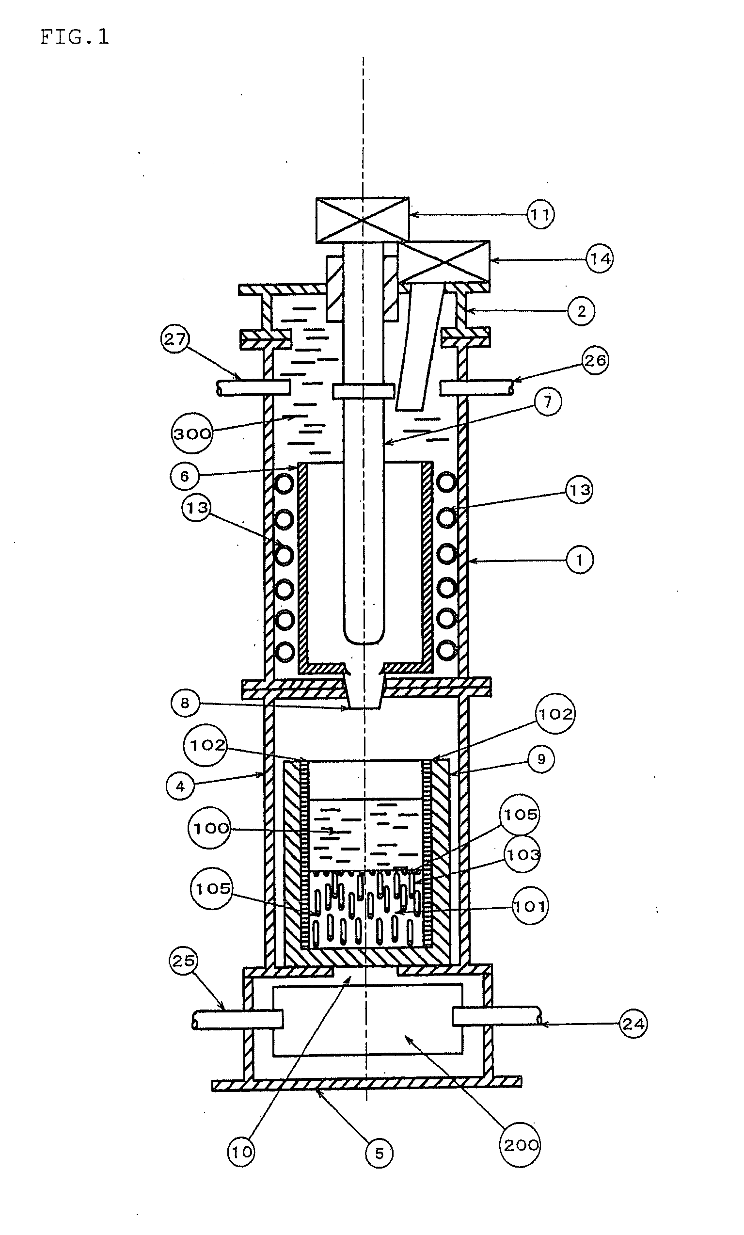
[0122]FIG. 2 is a schematic view showing an example of a vertical-type apparatus for producing a porous continuous body 104 using continuous casting method. The apparatus of FIG. 2 includes a heating unit container 1 for heating and melting a porous body-forming material; and, vertically disposed, a solidification adjusting unit container 4 and a cooling unit container 5. The molten raw material 100 that has passed through the continuous casting mold 12 moves downward while being cooled, and is solidified to form a porous continuous body 104. In the cooling unit container 5, the auxiliary cooling unit 17 is constantly cooling the material with the coolant water 200 to increase the temperature gradient, so as to align the pores 103 continuously growing inside the porous continuous body 104 in one direction, while the porous continuous bodies 104 are pulled out downward.

[0123]In the raw material supplying unit 14 disposed above the container cover 2, a raw material ha...

embodiment 3

(iii) Embodiment 3

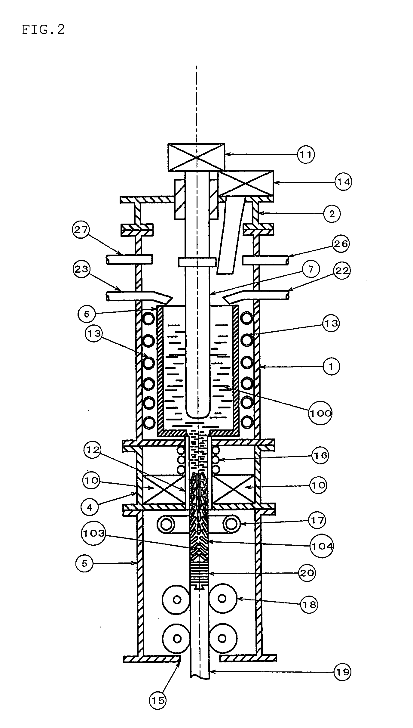
[0125]FIG. 3 is a schematic view showing an example of a horizontal-type apparatus for producing a porous continuous body 104 using continuous casting method, and pulling out the porous continuous body 104 in the horizontal direction. The apparatus of FIG. 3 includes a heating unit container 1 and a heat-retention unit container 3, which are vertically disposed; and, horizontally disposed, a solidification adjusting unit container 4 and a cooling unit container 5 having an auxiliary cooling unit 17. This FIG. 3 apparatus adopts the same heating method as that of the apparatuses of FIG. 1 and FIG. 2. The gas-forming compound 102 is added to the molten raw material 100 in the heat-retention container 21 inside the heat-retention adjusting unit container 3 via the compound supplying unit 22. At this time, by supplying an inactive gas via a stirring unit 23 and thereby stirring the molten raw material, the dissociation of the gas-forming compound 102 is facilitated.

[01...


PUM

PropertyMeasurementUnit
Temperatureaaaaaaaaaa
Pressureaaaaaaaaaa
Solubility (mass)aaaaaaaaaa

Abstract

The present invention provides a process for producing a porous body which comprises dispersing a gas-forming compound in a molten porous body-forming material, and then solidifying the molten material. With this process, the present invention enables manufacture of high quality and highly uniform porous bodies even under an atmospheric pressure, without requiring high pressure ambience.

Description

TECHNICAL FIELD[0001]The present invention relates to a process for producing a porous body.BACKGROUND ART[0002]As a porous body production method, a method for producing porous bodies with control over pore orientation, pore size, porosity etc. has been known. For example, according to one disclosed art, a mixed gas obtained by adding an inactive gas such as argon, helium, etc. to hydrogen, nitrogen, oxygen etc. is dissolved in a molten metal material under pressure, and then porous bodies are formed with control over temperature, pressure, solidification rate by cooling etc. (see Patent Document 1, 2 etc.)[0003]However, because this method is incapable of controlling a gas bubble generation nuclei that is necessary for pore growth, the nuclei formation becomes uneven; therefore, the pores produced become uneven. Moreover, since the gas is dissolved in a molten metal under pressure, this production method must be performed in a pressure vessel, which requires a complicated and unsa...

Claims


Application Information

Patent Timeline
IPC IPC(8): B29C67/20C22C38/00C22C23/00C22C9/00C22C21/00C01B33/02B22D27/00
CPCB22D11/00B22D11/11B22D11/1213C22C2001/086C01B33/02C04B38/0087C22C1/08B22D41/186C22C1/086C04B38/02B22D25/02
Inventor NAKAJIMA, HIDEOIDE, TAKUYA
Owner LOTUS ALLOY
Why Eureka
Try Eureka