[0007]In view of the above problem, the present invention has been accomplished and has an object of providing a low-cost gas detection apparatus reducing electrical
power consumption.
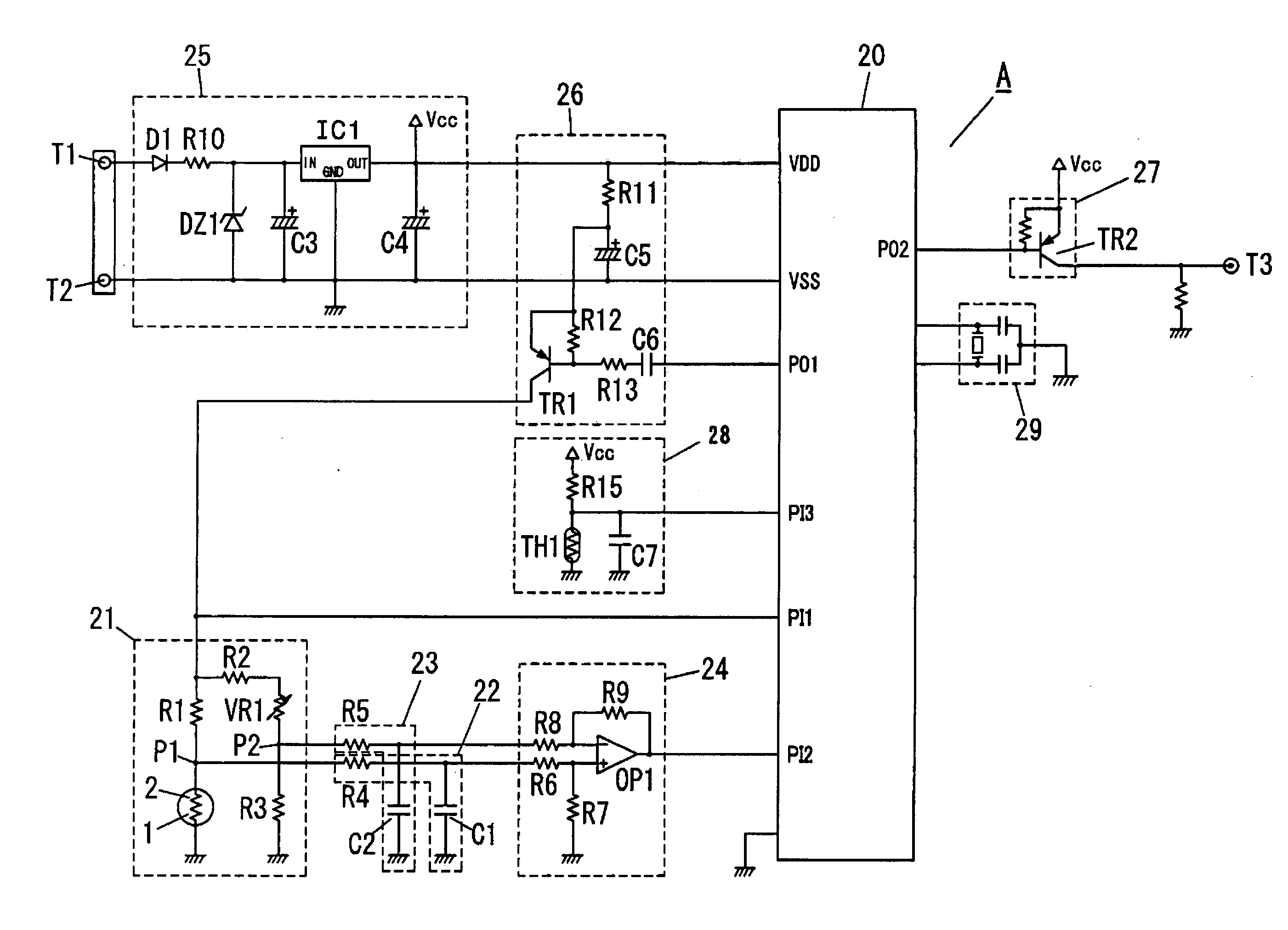
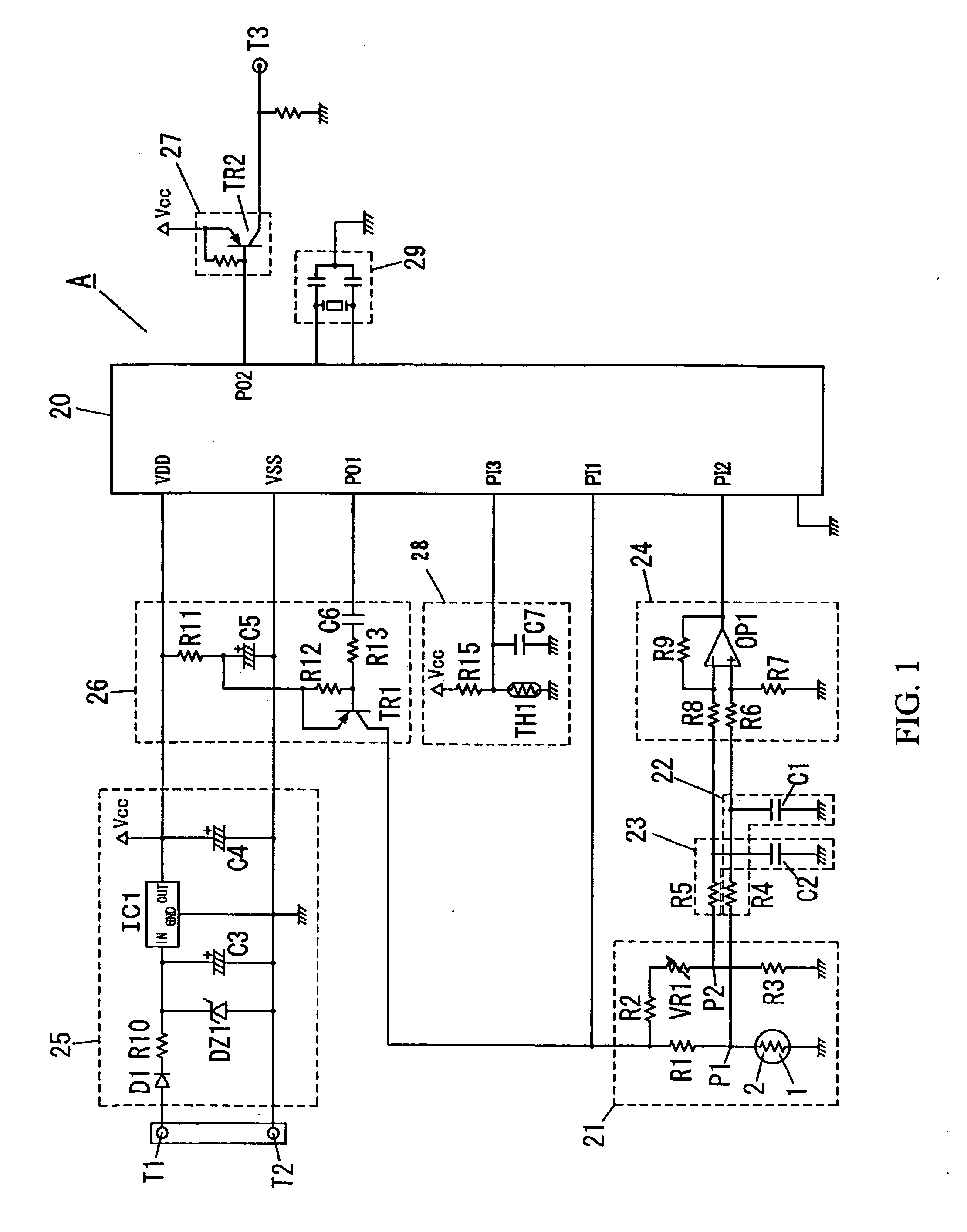
[0009]According to this invention, the heater voltage application circuit is configured to apply the pulsed heater voltage having the cycle shorter than the thermal
time constant of the gas sensing unit across the series circuit composed of the detection resistor and the load resistor, for supplying the detection resistor with a predetermined voltage to heat the detection resistor up to a specific temperature. This configuration does not necessitate any circuit for stepping down a
power supply voltage to a mean voltage applied to the detection resistor, not requiring the use of electrical power for the step-down of the
power supply voltage, thereby enabling to provide the gas detection apparatus reducing electrical
power consumption. Moreover, this configuration does not require any complex circuit such as a switching
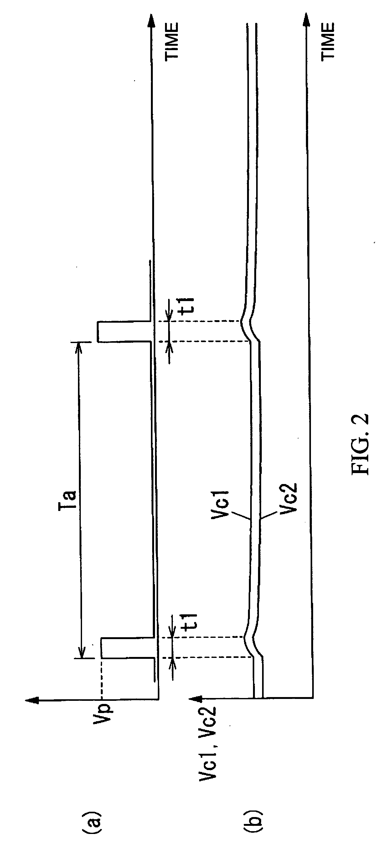
regulator circuit for generating a voltage applied to the detection resistor, enabling to reduce the cost of the gas detection apparatus as well as minimize space for mounting thereon, thereby providing a compact gas detection apparatus. When being applied to the detection resistor, the pulsed heater voltage generates a pulsed voltage across the detection resistor. Since the generated pulsed voltage slightly varies its peak voltage in response to a concentration of the flammable gas, the heater voltage needs to be applied in a
short cycle for stabilizing a temperature of the heated detection resistor, necessitating an expensive
amplifier having a
rapid response rate because ordinary amplifiers are unable to follow the variation of the voltage across the detection resistor. In contrast, the present invention according to claim 1 utilizes the integrated voltage obtained by an integrating circuit as the output
signal of the gas sensing unit, not requiring any expensive element having a
rapid response rate for determination of the
gas concentration by the output signal, thereby enabling to utilize inexpensive components for configuring the gas detection circuit.
[0011]According to this invention, the heater voltage application circuit is configured to apply the pulsed heater voltage having the cycle shorter than the thermal
time constant of the gas sensing unit across the series circuit composed of the detection resistor and the reference resistor, for supplying the detection resistor and the reference resistor with a predetermined voltage to heat the detection resistor and the reference resistor up to a specific temperature. This configuration does not necessitate any circuit for stepping down a
power supply voltage to a mean voltage applied to the detection resistor and the reference resistor, not requiring the use of electrical power for the step-down of the power supply voltage, thereby enabling to provide the gas detection apparatus reducing electrical
power consumption. Moreover, this configuration does not require any complex circuit such as a switching
regulator circuit for generating a voltage applied to the detection resistor and the reference resistor, enabling to reduce the cost of the gas detection apparatus as well as minimize space for mounting thereon, thereby providing the compact gas detection apparatus. When being applied to the detection resistor and the reference resistor, the pulsed heater voltage generates a pulsed voltage across the detection resistor and the reference resistor. Since the generated pulsed voltage slightly varies its peak voltage in response to the concentration of the flammable gas, the heater voltage needs to be applied in a
short cycle for stabilizing temperature of the heated detection resistor and the heated reference resistor, necessitating the expensive
amplifier having the rapid response rate because ordinary amplifiers are unable to follow the variation of the voltage across the detection resistor. In contrast, the present invention according to claim 2 utilizes the integrated voltage obtained by the integrating circuit as the output signal of the gas sensing unit, not requiring any expensive element having the rapid response rate for determination of the
gas concentration by the output signal, thereby enabling to utilize inexpensive components for configuring the gas detection circuit.
[0013]The gas detection apparatus of this invention outputs the voltage, which is integrated by the integrating circuit unit and then amplified by the amplification circuit unit, as the output signal of the gas sensing unit, increasing the output
signal level of the gas sensing unit, and thereby enabling to detect the gas with
high resolution and accuracy.
[0015]According to this invention, the
bridge circuit is configured by the series connection of a plurality of the bridge resistors between both ends of the series circuit composed of the detection resistor and the reference resistor. The gas detection apparatus in the present invention integrates the voltage at the connection point between the detection resistor and the reference resistor by the first integrating circuit unit as well as the voltage at the connection point between the bridge resistors by the second integrating circuit unit, and then amplifies the differential voltage between the output voltages of both integrating circuit units by the differential amplification circuit unit. With the use of the
bridge circuit, the gas detection apparatus of the present invention gives a large output indicative of voltage changes at the connection point between the detection resistor and the reference resistor by the differential amplification circuit unit, thereby enabling to detect the gas with
high resolution and accuracy.

