
Method and apparatus for atomic layer deposition using an atmospheric pressure glow discharge plasma

a glow discharge plasma and atomic layer technology, applied in the field of methods, can solve problems such as inability to deposition material on temperature sensitive substrates, and achieve the effect of higher reaction rates and higher productivity

Inactive Publication Date: 2009-12-31
FUJIFILM MFG EURO
View PDF38 Cites 314 Cited by
  • Summary
  • Abstract
  • Description
  • Claims
  • Application Information

AI Technical Summary

Benefits of technology

[0015]Use of an atmospheric plasma obviates the need to work at very low pressure. All steps of the ALD process can now be executed at around atmospheric pressure. Hence no complex constructions are necessary to obtain a vacuum or near vacuum at the substrate surface during processing.
[0016]In an embodiment, the substrate is a flexible substrate of polymeric material. The present treatment method is particularly suited for such a substrate material, with regard to the operating environment (temperature, pressure) allows the use of such material without necessitating further measures. The present electrode structure also allows a wider gap between electrodes than in prior art systems, allowing using a substrate with a thickness of up to 2 mm.
[0020]In a specific embodiment of this invention the atmospheric plasma is an atmospheric pressure glow discharge plasma. In a further embodiment, the atmospheric pressure glow discharge plasma is stabilized by stabilization means counteracting local instabilities in the plasma.
[0021]Executing an ALD process at atmospheric pressure has an additional advantage in that higher reaction rates are possible, which can lead to a higher productivity. With the present method, parallel thin film layers for example as thin as one molecular layer may be obtained, wherein the films have a comparable or better performance to films produced by prior art methods.
[0038]In a further embodiment, the plasma generator is arranged to generate an atmospheric pressure glow discharge plasma. The plasma generator may further comprise stabilization means for stabilizing the pulsed atmospheric glow discharge plasma to counteract local instabilities in the plasma.

Problems solved by technology

), are not suitable for deposition of material on temperature sensitive substrates, such as polymer substrates.

Method used


Image

  • Method and apparatus for atomic layer deposition using an atmospheric pressure glow discharge plasma
  • Method and apparatus for atomic layer deposition using an atmospheric pressure glow discharge plasma
  • Method and apparatus for atomic layer deposition using an atmospheric pressure glow discharge plasma

Examples


example 1

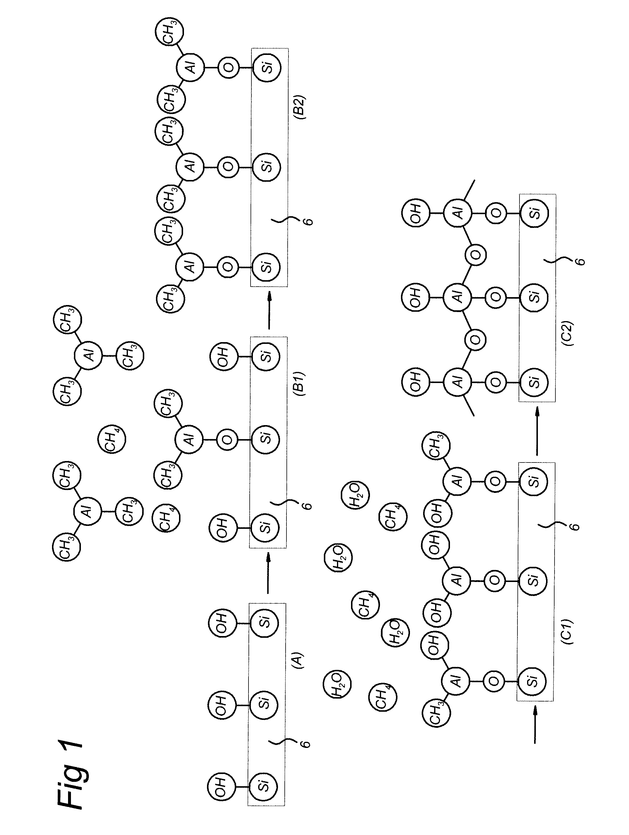
[0097]Step A: The polymer surface is made susceptible to the ALD reaction by a short CVD step in which a very thin film of SiO2 is deposited from TEOS (tetraethoxysilane) or HMDSO (hexamethyldisiloxane). The thin SiO2 surface is terminated via Si—OH groups, thus forming a surface layer comparable to the substrate 6 shown in FIG. 1 at reference (A).

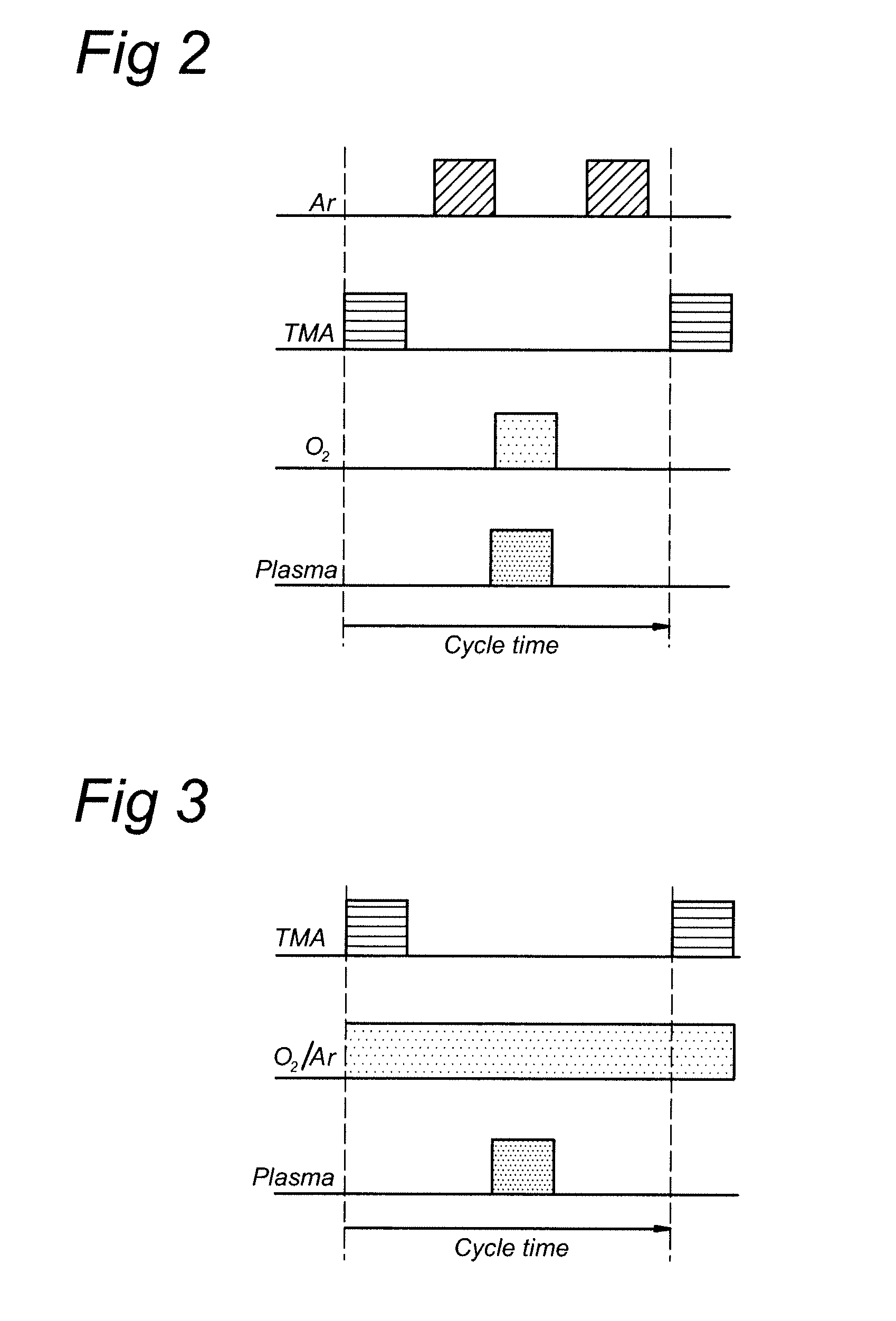
[0098]Step B. In a first embodiment pulses of TMA precursor and oxygen gas are alternated while maintaining a purge step in between precursor and reactive agent to flush the electrode gap (above the surface of the substrate 6). The purge step may be performed using an inert gas, in this case Ar. This is shown schematically in the time plot of FIG. 2, which shows the respective gas flows and APG plasma pulse for a single cycle time period. Due to atmospheric pressure TMA is reacting very quickly with the hydroxyl groups. Typical concentration of TMA is 200 mg / hr.

[0099]Step C: After flushing the gap to remove the precursor the oxygen is inse...

example 2

[0102]In a further example, a continuous reactive (for instance 10% oxygen in argon) gas stream is used, during both step A and step B, while a pulsed TMA precursor treatment is used, as shown schematically in FIG. 3. During the entire cycle time of 0.8 sec, Argon and Oxygen are introduced in a continuous manner. The plasma conditions in this embodiment are the same as described with the previous embodiment.

treatmentOxygenGas compositiontimePlasma1) Argon + TMA1 slm10 slm + 200 mg / hr0.5off2) Argon1 slm10 slm0.2off3) Argon1 slm10 slm0.1on

example 3

[0103]In this example, also the input of TMA is in a continuous manner, and only the APG plasma is applied in a pulsed manner to enhance the ALD process, as shown in the time plot of FIG. 4. To reduce chemical vapor reaction the TMA flow should be limited to a region very nearby the surface 6 on which the Al2O3 has to be deposited. This embodiment allows for obtaining a very short cycle time of only 0.3 sec, as shown in the following table.

precursorOxygenGas + prectreatment timePlasma1) Argon200 mg / hr1 slm10 slm0.2off2) Argon200 mg / hr1 slm10 slm0.1on

[0104]The plasma conditions are again the same as in the previous two examples.


PUM

PropertyMeasurementUnit
thicknessaaaaaaaaaa
temperatureaaaaaaaaaa
pressureaaaaaaaaaa

Abstract

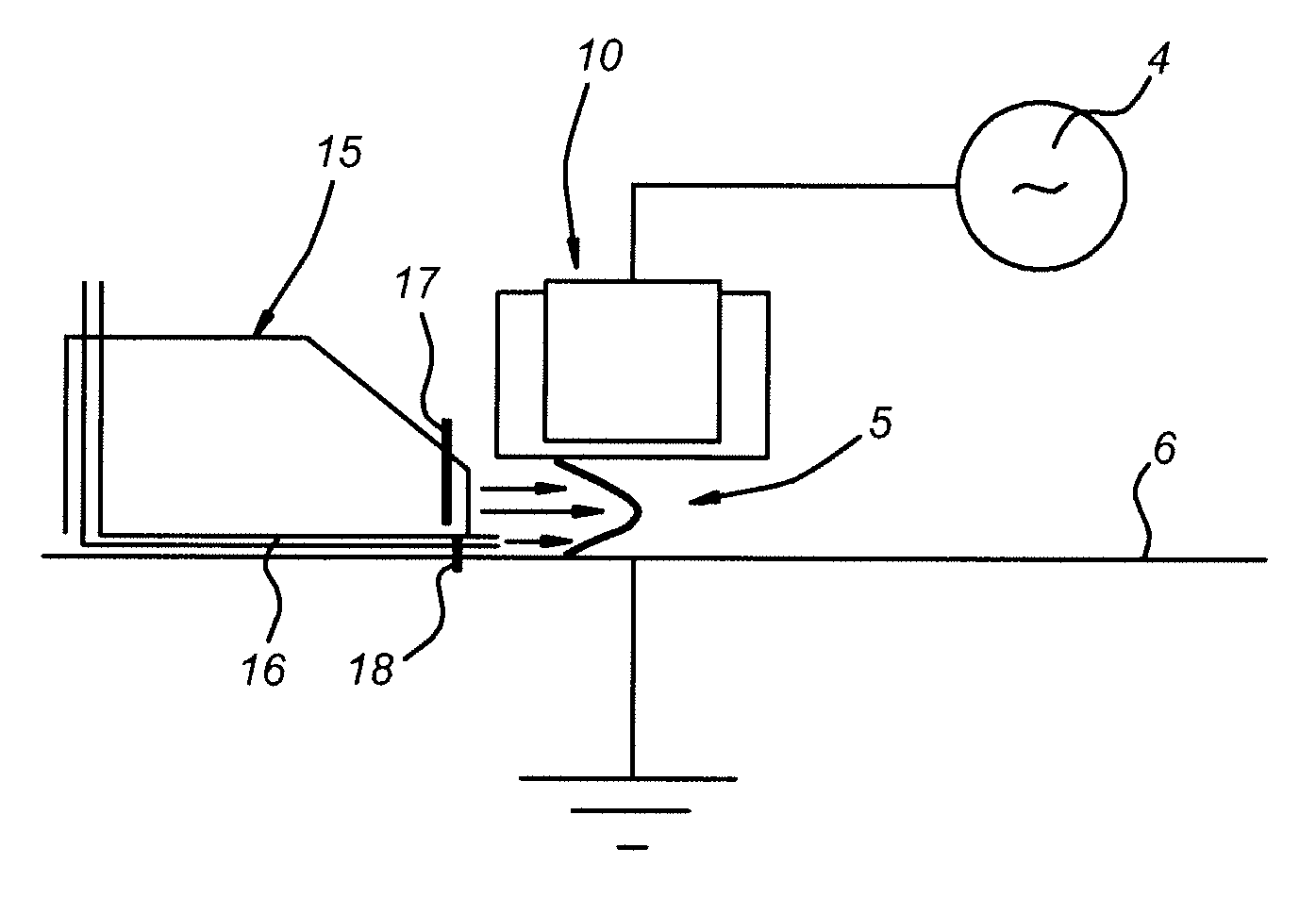
Apparatus and method for atomic layer deposition on a surface of a substrate (6) in a treatment space. A gas supply device (15, 16) is present for providing various gas mixtures to the treatment space. The gas supply device (15, 16) is arranged to provide a gas mixture with a precursor material to the treatment space for allowing reactive surface sites to react with precursor material molecules to give a surface covered by a monolayer of precursor molecules attached via the reactive sites to the surface of the substrate. Subsequently, a gas mixture comprising a reactive agent capable to convert the attached precursor molecules to active precursor sites is provided. A plasma generator (10) is present for generating an atmospheric pressure plasma in the gas mixture comprising the reactive agent.

Description

FIELD OF THE INVENTION[0001]The present invention relates to a method for atomic layer deposition on the surface of a substrate. In a further aspect, the present invention relates to an apparatus for atomic layer deposition on the surface of a substrate including an atmospheric plasma system. In an even further aspect of this invention, the apparatus is used for the deposition of a chemical substance or element.PRIOR ART[0002]Atomic layer deposition (ALD) is used in the art to provide layers of a material on the surface of a substrate. Different from chemical vapor deposition (CVD) and physical vapor deposition (PVD), atomic layer deposition (ALD) is based on saturated surface reactions. The intrinsic surface control mechanism of ALD process is based on the saturation of an individual, sequentially-performed surface reaction between the substrate reactive sites and precursor molecules. The saturation mechanism makes the film growth rate directly proportional to the number of reactio...

Claims


Application Information

Patent Timeline
Patent Type & Authority Applications(United States)
IPC IPC(8): B32B27/00C23C16/513C23C16/455C23C16/509
CPCC23C16/45542C23C16/515C23C16/45595C23C16/45551
Inventor DE VRIES, HINDRIK WILLEMVAN DE SANDEN, MAURITIUS CORNELIUS MARIACREATORE, MARIADRIANAKESSELS, WILHELMUS MATHIJS MARIE
Owner FUJIFILM MFG EURO
Learn More