
Cryogenic liquid storage system for a spacecraft

Active Publication Date: 2010-01-07
SN DETUDE & DE CONSTR DE MOTEURS DAVIATION S N E C M A
View PDF14 Cites 19 Cited by
  • Summary
  • Abstract
  • Description
  • Claims
  • Application Information

AI Technical Summary

Benefits of technology

[0018]The invention seeks in particular to reduce the structural index of the tanks and the associated fluid systems and to improve the safety factor under pressure in such a manner as to enable personnel to be present without restriction after a tank has been filled.
[0036]Storing a component such as xenon in the liquid state in a spacecraft tank presents several advantages:
[0037]density is higher (3057 kilograms per cubic meter (kg / m3) instead of 1200 kg / m3 to 1600 kg / m3), thereby implying a tank of smaller volume;
[0038]storage pressure can be controlled so as to correspond to the feed pressure of the thrusters, thereby avoiding the use of high-pressure expanders;

Problems solved by technology

Nevertheless, the weight of the insulation required for a tank of that type is very great and makes it difficult for use in a propulsion application.
Nevertheless, no provision is made for use in interplanetary missions of long duration.
This relatively small percentage (5.1%) is obtained at the cost of technology that is very difficult.
In general, systems fitted with plasma or ion thrusters fed with xenon stored in the supercritical state in high-pressure tanks present the following drawbacks:the dry weight percentage of the storage is higher than it is with chemical propulsion;it is necessary to interpose high-pressure valves and an expander between the tank and the thrusters, thereby increasing weight and reducing reliability because of the increased number of components; andthe safety factor of the tank is generally too low to allow personnel to be present without restriction after the tank has been filled.
Both xenon gas and the wall made of composite material present low thermal conductivity, such that filling a supercritical tank too quickly leads to the xenon being heated excessively by quasi-adiabatic compression.

Method used


Image

  • Cryogenic liquid storage system for a spacecraft
  • Cryogenic liquid storage system for a spacecraft
  • Cryogenic liquid storage system for a spacecraft

Examples


Embodiment Construction

[0052]The invention relates to tanks for storing an inert gas such as xenon, krypton, neon, or argon in the liquid state for feeding to electric (plasma or ion) thrusters for satellites or planetary probes.

[0053]The invention also applies to storing cryogenic fuel components such as liquid oxygen in spacecrafts.

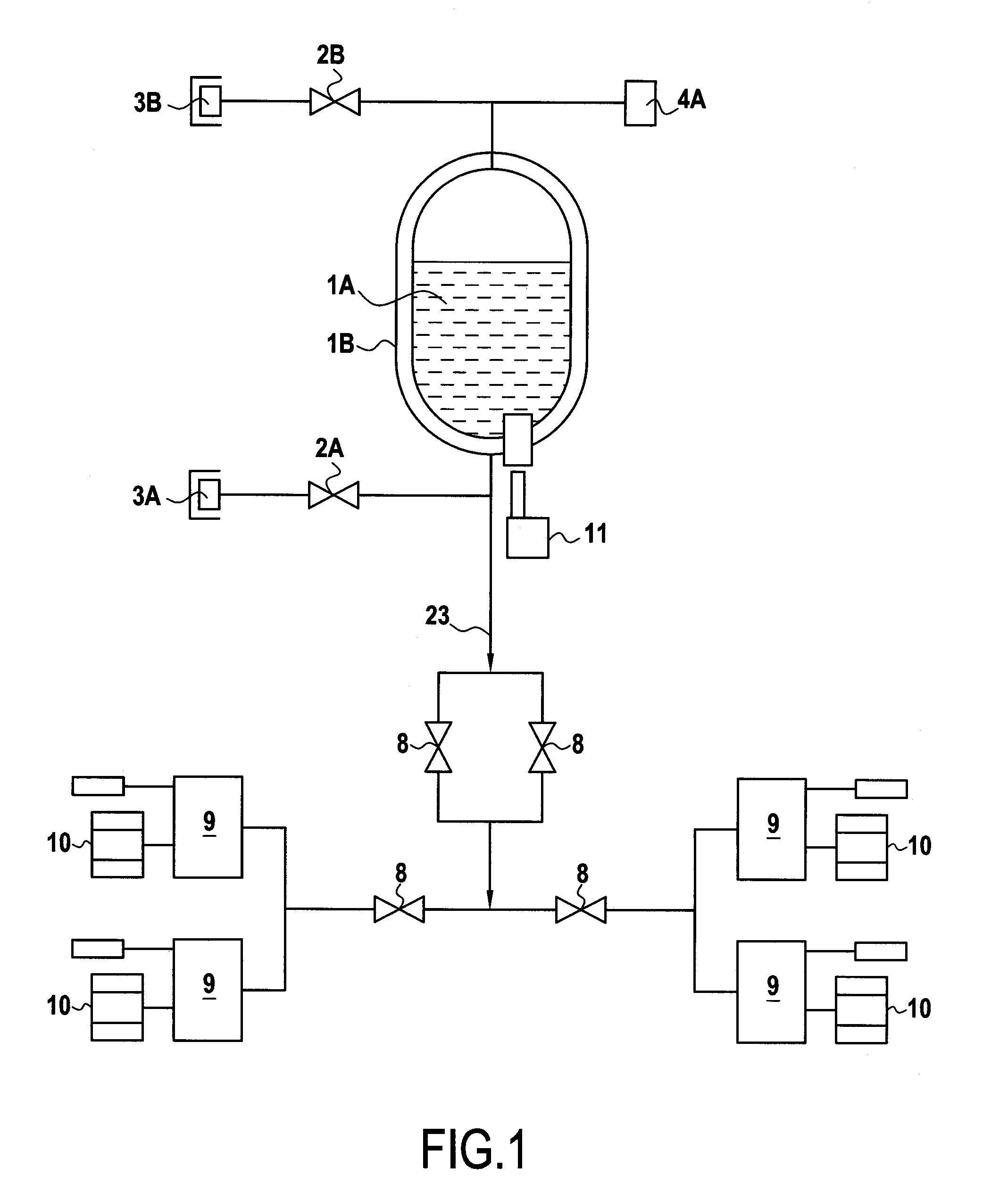
[0054]FIG. 1 shows an example of the invention applied to an electric propulsion system.

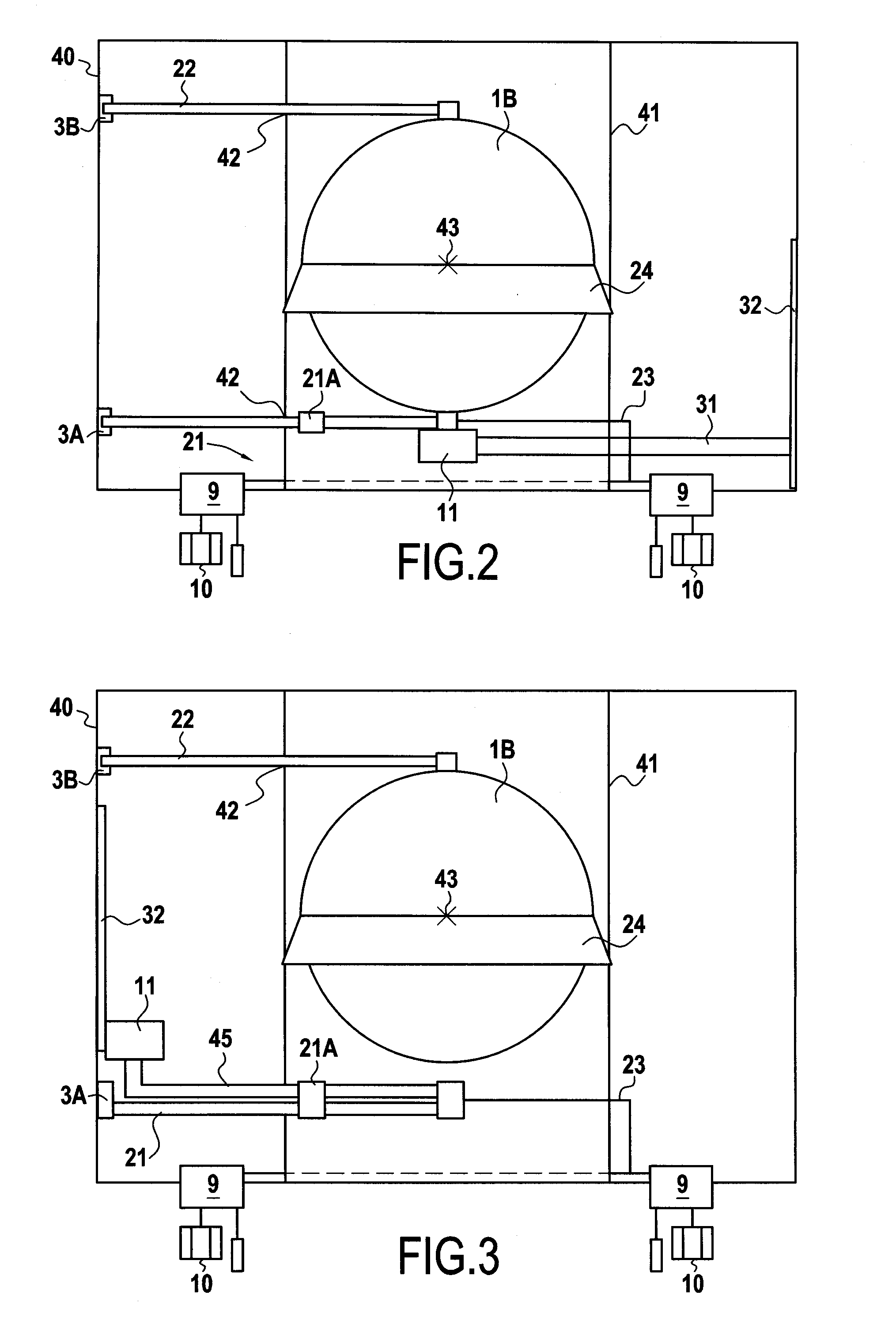
[0055]A tank 1A for storing cryogenic liquid is contained within an outer casing 1B in which a vacuum is established.

[0056]A cryorefrigerator 11 cools the liquid contained in the tank 1A, which liquid may be xenon, krypton, neon, or argon, for example.

[0057]Reference 2A designates a valve for filling / emptying the tank 1A with liquid via a liquid filling / emptying orifice 3A.

[0058]A valve 2B enables the vapor in the tank 1A to be bled off to a vapor-purge orifice 3B.

[0059]A low pressure sensor 4A serves to monitor the vapor pressure inside the tank 1A.

[0060]By means of a line 23, the tank 1A...


PUM

PropertyMeasurementUnit
Angleaaaaaaaaaa
Angleaaaaaaaaaa
Diameteraaaaaaaaaa

Abstract

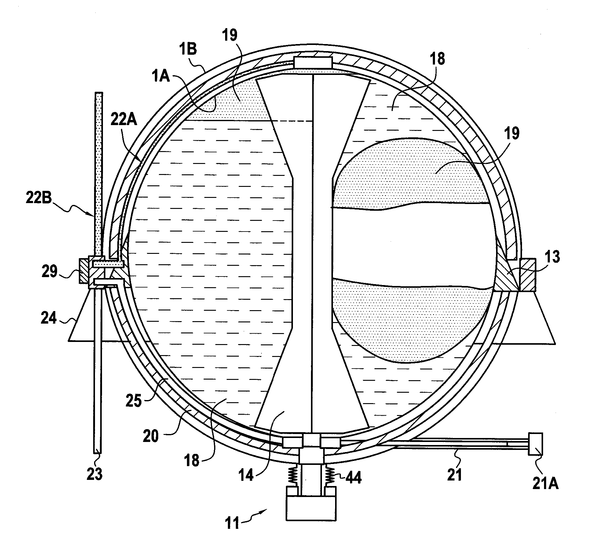
A cryogenic liquid storage system for a spacecraft comprising at least one liquid tank with an outer casing and an evacuated space arranged between the tank and the outer casing. The system further comprises a propellant management device made of material that is a good conductor of heat and that is cooled by a cryorefrigerator to localize the liquid inside the tank when in microgravity, a filler pipe situated in the portion of the tank that is at the bottom when the tank is on the ground, and that is surrounded by an evacuated insulating double wall and a purge pipe connecting the tank to the outer casing and presenting an internal length that is not less than half the diameter of the tank.

Description

FIELD OF THE INVENTION[0001]The present invention relates to a cryogenic liquid storage system for a spacecraft, the system comprising at least one liquid tank.PRIOR ART[0002]Space tanks are already known for storing superfluid liquid helium for the purpose of cooling detectors and telescopes in infrared astronomy satellites.[0003]Nevertheless, the weight of the insulation required for a tank of that type is very great and makes it difficult for use in a propulsion application.[0004]Furthermore, the use of liquid hydrogen and oxygen for missions in earth orbit or for interplanetary missions has been analyzed for many years, in particular in the United States of America. It is necessary to establish a liquid / vapor phase boundary under microgravity making use of the same principles as surface tension tanks for satellites. Thermal insulation is simpler and lighter in weight than it is with liquid helium tanks.[0005]Document EP 1 248 031 A2 describes an example of a tank of that type fo...

Claims


Application Information

Patent Timeline
IPC IPC(8): F25B9/14F17C5/02
CPCB64G1/12F17C2260/027B64G1/402B64G1/405F17C13/088F17C2205/013F17C2205/0161F17C2270/0194F17C2205/0192F17C2203/0663F17C2205/0323F17C2205/0338F17C2205/0391F17C2221/011F17C2221/016F17C2223/0115F17C2223/0161F17C2223/033F17C2223/035F17C2225/0115F17C2225/0161F17C2227/0135F17C2227/0353F17C2227/036F17C2227/0372F17C2227/0374F17C2250/043F17C2250/0491F17C2250/0636B64G1/401B64G1/413B64G1/4021
Inventor VALENTIAN, DOMINIQUE
Owner SN DETUDE & DE CONSTR DE MOTEURS DAVIATION S N E C M A
Learn More