Loop antenna input circuit for am and am radio receiver using the same

a technology of loop antenna and radio receiver, which is applied in the direction of loop antenna, high frequency amplifier, transmission, etc., can solve the problems of increasing current noise, hard to provide transformers or the like in ic chips, etc., and achieves the effect of preventing current noise, easy integration of antenna input circuit, and increasing the impedance of loop antenna itsel

Inactive Publication Date: 2010-01-07
NSC CO LTD +1
View PDF6 Cites 50 Cited by
  • Summary
  • Abstract
  • Description
  • Claims
  • Application Information

AI Technical Summary

Benefits of technology

[0011]In order to solve the problems, it is an object of the present invention to eliminate the necessity of an impedance converting circuit using a transformer or the like without increasing a current noise in a loop antenna input circuit of an AM radio receiver.
[0014]According to the present invention having the structure described above, also in the case in which a loop antenna having a low impedance is used, an input signal can be received by a field effect transistor having a high impedance which is directly connected to the loop antenna. Therefore, it is not necessary to use an impedance converting circuit constituted by a transformer or the like for carrying out a conversion into a high impedance. Thus, it is possible to easily integrate an antenna input circuit. Moreover, it is not necessary to increase the impedance of the loop antenna itself. Therefore, it is also possible to prevent a current noise from being made. Furthermore, the differential amplifying circuit constituted by the field effect transistor can lessen the occurrence of the noise, thereby amplifying only the input signal efficiently.

Problems solved by technology

However, it is hard to provide the transformer or the like in an IC chip.
For this reason, there is a problem in that the transformer or the like is to be constituted as an external component of the IC chip.
However, there is a problem in that a current noise is increased as a result.

Method used


Image

  • Loop antenna input circuit for am and am radio receiver using the same
  • Loop antenna input circuit for am and am radio receiver using the same
  • Loop antenna input circuit for am and am radio receiver using the same

Examples


Embodiment Construction

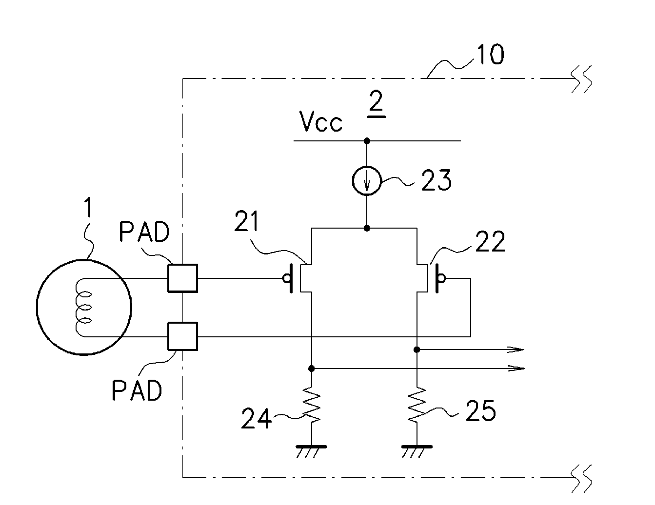
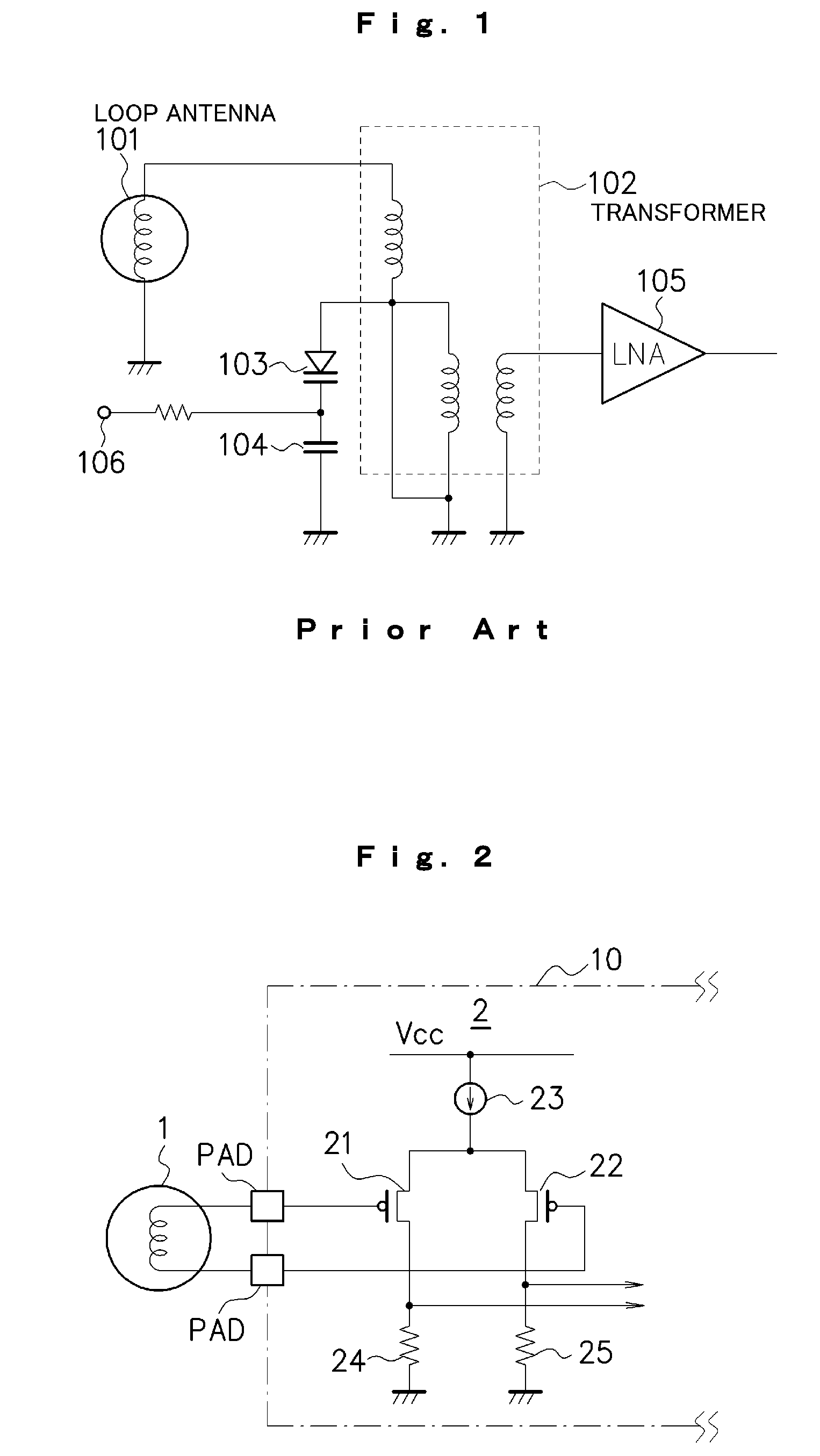
[0018]An embodiment according to the present invention will be described below with reference to the drawings. FIG. 2 is a diagram showing an example of a structure of a main part in an AM radio receiver using a loop antenna input circuit according to the present embodiment. As shown in FIG. 2, the AM radio receiver according to the present embodiment includes a loop antenna 1 and a differential amplifier 2 which is directly connected to the loop antenna 1 as a structure of a front end portion thereof. The differential amplifier 2 is integrated into a single IC chip 10 through a CMOS (Complementary Metal Oxide Semiconductor) process or a Bi-CMOS (Bipolar-CMOS) process, for example.

[0019]The differential amplifier 2 according to the present embodiment includes two p-MOSFETs (field effect transistors) 21 and 22 to be amplifying elements, a constant current source 23 connected between the p-MOSFETs 21 and 22 and a power supply Vcc, and two resistors 24 and 25 connected between the p-MO...


PUM


Abstract

p-MOSFETs (21) and (22) are used as amplifying elements for amplifying a signal input from a loop antenna (1) and are directly connected to the loop antenna (1). Thus, the signal input from the loop antenna (1) can be received in a high impedance through the p-MOSFETs (21) and (22). Consequently, a transformer for carrying out a conversion into a high impedance or the like is not required, and furthermore, the impedance of the loop antenna 1 itself does not need to be increased, thereby suppressing the occurrence of a current noise.

Description

TECHNICAL FIELD[0001]The present invention relates to a loop antenna input circuit for AM and an AM radio receiver using the same, and more particularly to an AM radio receiver using a loop antenna as an antenna.BACKGROUND ART[0002]An antenna to be used in a broadcasting signal receiving device such as a radio receiver includes a loop antenna. The loop antenna is based on a principle for extracting an induced electromotive force depending on a change in a magnetic field in a coil formed by winding a conductor several times. For example, in an AM radio receiver for a home audio, a loop antenna input circuit includes a tuning transformer constituted by a primary coil and a secondary coil coupled electromagnetically thereto and a variable capacitance diode and a capacitor which are connected in parallel with the primary coil.[0003]FIG. 1 is a diagram showing a part of a structure of a conventional AM radio receiver using a loop antenna. In FIG. 1, 101 denotes a loop antenna, 102 denote...

Claims


Application Information

Patent Timeline
Patent Type & Authority Applications(United States)
IPC IPC(8): H04B1/06H01Q7/00
CPCH01Q7/00H03F1/565H04B1/18H03F3/45H03F3/189
Inventor IKEDA, TAKESHIMIYAGI, HIROSHI
Owner NSC CO LTD
Why Eureka
Try Eureka