Exhaust gas purification apparatus for engine

a technology of exhaust gas purification apparatus and exhaust gas, which is applied in the direction of exhaust treatment electric control, electrical control, separation process, etc., can solve the problem that nox in exhaust gas cannot be effectively removed, and achieve the effect of reducing nox emission, reducing nox emission, and increasing the temperature of selective reduction catalyst 21

Inactive Publication Date: 2010-01-14
HINO MOTORS LTD
View PDF10 Cites 26 Cited by
  • Summary
  • Abstract
  • Description
  • Claims
  • Application Information

AI Technical Summary

Benefits of technology

[0015]In the exhaust gas purification apparatus for an engine, the after injection can increase hydrocarbon in exhaust gas and burn the hydrocarbon to raise the temperature of exhaust gas flowing out of the engine 11 to the exhaust pipe 16. Also, the post injection can cause the hydrocarbon increased in exhaust gas to undergo oxidation reaction in the oxidation catalyst 53 provided on the upstream side of the particulate filter 51 to further raise the temperature of exhaust gas, by which the temperature of the selective reduction catalyst 21 can be increased rapidly.
[0016]In the exhaust gas purification apparatus for an engine, since the liquid injection nozzle, the mixer, and the selective reduction catalyst are provided, when the urea-based liquid is injected from the injection nozzle, the urea-based liquid flows into the mixer, being mixed with exhaust gas, and reaches the selective reduction catalyst. In the selective reduction catalyst, the urea-based liquid is hydrolyzed, and ammonia yielded by the hydrolysis reduces NO and NO2, by which the emission of NOx is reduced. The ammonia purification catalyst provided in the exhaust pipe on the downstream side of the selective reduction catalyst oxidizes ammonia passing through the selective reduction catalyst without being used as a reducing agent, by which the ammonia is converted to harmless N2 and H2O so that the ammonia is effectively prevented from being discharged to the atmosphere.
[0017]On the other hand, when the fuel is injected into the cylinder after the top dead center of piston by the fuel injection device, the fuel burns in the exhaust pipe, or undergoes oxidation reaction in the oxidation catalyst provided on the upstream side of the particulate filter to remarkably raise the temperature of exhaust gas, by which the temperature of the selective reduction catalyst on the downstream side of the particulate filter is increased rapidly. For this purpose, when the temperature sensor detects that the selective reduction catalyst has a temperature at which the urea-based liquid does not hydrolyze, the controller controls the fuel injection device so that the fuel is injected into the cylinder after the top dead center of piston. Thereby, the temperature of the selective reduction catalyst is increased rapidly, and therefore NOx in exhaust gas can be removed effectively.
[0018]Also, since the diesel particulate filter is provided in the exhaust pipe on the exhaust gas upstream side of the liquid injection nozzle, the particulate filter captures particulates in exhaust gas of the diesel engine to effectively prevent the particulates from being discharged to the outside. If the quantity of captured particulates increases, the resistance of exhaust gas passing through the particulate filter increases. However, by injecting the fuel into the cylinder after the top dead center of piston and by burning the fuel, the particulate filter can be regenerated.

Problems solved by technology

However, ammonia yielded by the hydrolysis of urea-based liquid functions as a reducing agent only when the temperature of exhaust gas is relatively high.
For this reason, in the exhaust gas purification apparatus using the selective reduction catalyst in the exhaust pipe, there remains an unsolved problem in that NOx in exhaust gas cannot be removed effectively when the temperature of exhaust gas is relatively low.

Method used


Image

  • Exhaust gas purification apparatus for engine
  • Exhaust gas purification apparatus for engine

Examples


Embodiment Construction

[0021]A best mode for carrying out the invention will now be described with reference to the accompanying drawings.

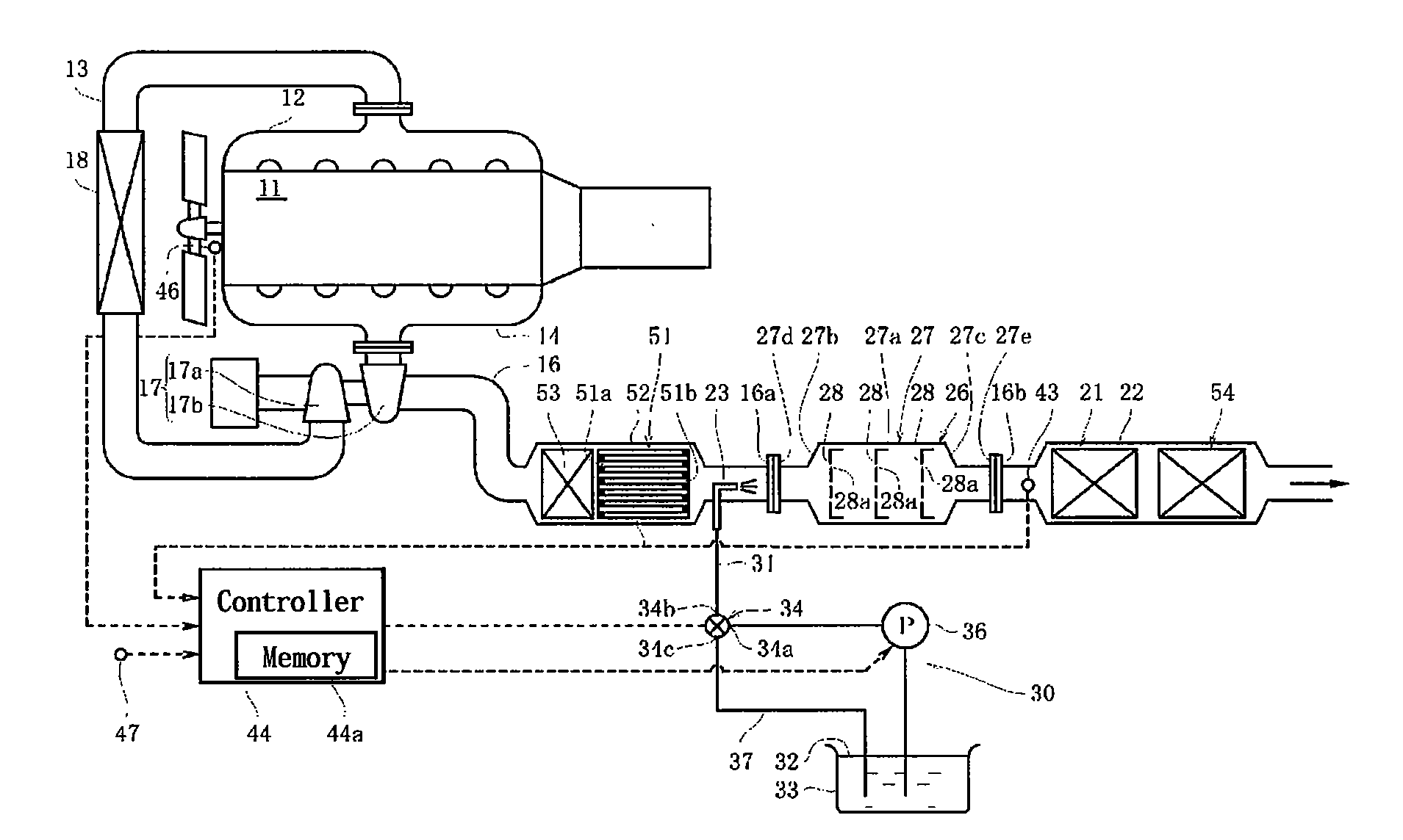
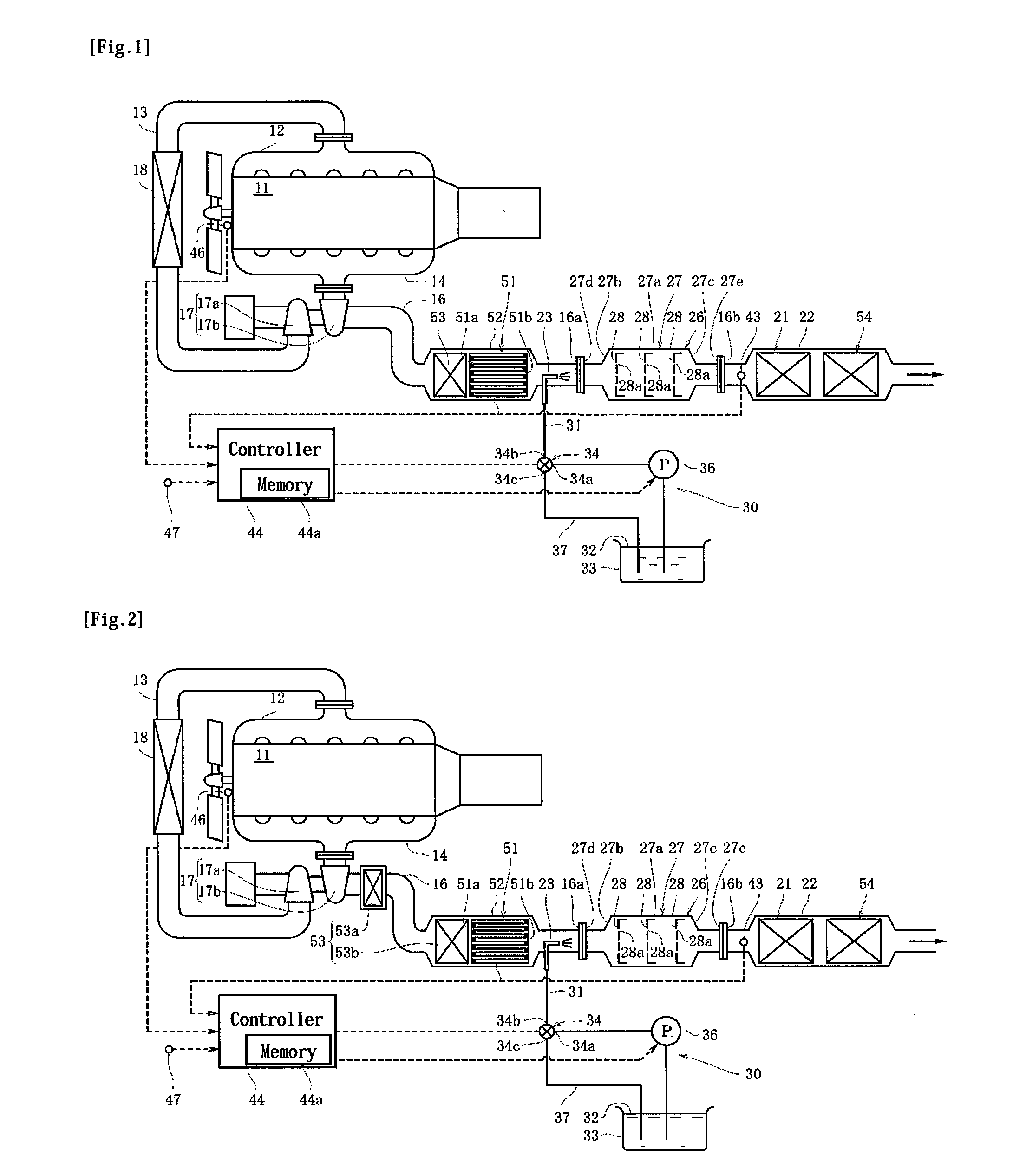
[0022]As shown in FIG. 1, the intake port of a diesel engine 11 is connected with an intake pipe 13 via an intake manifold 12, and the exhaust port thereof is connected with an exhaust pipe 16 via an exhaust manifold 14. The intake pipe 13 is provided with a compressor 17a of a turbocharger 17 and an inter-cooler 18 for cooling intake air compressed by the turbocharger 17, and the exhaust pipe 16 is provided with a turbine 17b of the turbocharger 17. Although not shown, the rotary vane of the compressor 17a and the rotary vane of the turbine 17b are connected to each other by a shaft. The configuration is made such that the compressor 17a is rotated via the turbine 17b and the shaft by the energy of exhaust gas discharged from the engine 11, by which intake air in the intake pipe 13 is compressed by the rotation of the compressor 17a.

[0023]In the middle of the exhaust ...


PUM

PropertyMeasurementUnit
crank angleaaaaaaaaaa
temperatureaaaaaaaaaa

Abstract

There is provided an exhaust gas purification apparatus for an engine capable of effectively removing NOx in exhaust gas even when the temperature of exhaust gas is relatively low. The exhaust gas purification apparatus includes a selective reduction catalyst provided in an exhaust pipe, a liquid injection nozzle provided on the upstream side of the selective reduction catalyst, a liquid injecting means capable of injecting a urea-based liquid via the liquid injection nozzle, a controller, and a mixer. The apparatus further includes an ammonia purification catalyst provided on the downstream side of the selective reduction catalyst, a diesel particulate filter provided on the upstream side of the nozzle, an oxidation catalyst provided on the upstream side of the diesel particulate filter, and a temperature sensor for detecting the temperature of the selective reduction catalyst. A fuel injection device is configured so as to be capable of injecting fuel into a cylinder after the top dead center of piston, and when the temperature sensor detects that the selective reduction catalyst has a temperature not higher than a predetermined temperature, the controller controls the fuel injection device so that fuel is injected into the cylinder after the top dead center of piston.

Description

CROSS REFERENCE TO RELATED APPLICATION[0001]This is a U.S. national phase application under 35 U.S.C. § 371 of International Patent Application No. PCT / JP2007 / 067903 filed Sep. 14, 2007 and claims the benefit of Japanese Application No. 2006-255634 filed Sep. 21, 2006. The International Application was published on Mar. 27, 2008 as International Publication No. WO / 2008 / 035623 under PCT Article 21(2) the contents of these applications are incorporated herein in their entirety.TECHNICAL FIELD[0002]The present invention relates to an exhaust gas purification apparatus for an engine, which removes nitrogen oxides contained in exhaust gas of a diesel engine to purify the exhaust gas.BACKGROUND OF ART[0003]Conventionally, as an exhaust gas purification apparatus for reducing nitrogen oxides (hereinafter abbreviated as NOx) contained in exhaust gas of a diesel engine, there has been known an exhaust gas purification apparatus for a diesel engine, in which a selective reduction catalyst is ...

Claims


Application Information

Patent Timeline
Patent Type & Authority Applications(United States)
IPC IPC(8): F01N9/00F01N3/035
CPCB01D53/9418F01N13/0093B01D53/9477B01D53/9495B01D2251/2062B01D2257/406F01N3/035F01N3/106F01N3/2066F01N3/2892F01N11/002F01N2610/02F02B29/0425F02B37/00F02D41/0245F02D41/025F02D41/1446F02D41/405Y02T10/47Y02T10/24F01N13/009F01N13/0097B01D53/944Y02T10/12Y02T10/40
Inventor HOSOYA, MITSURUKAWADA, YOSHIHIRO
Owner HINO MOTORS LTD
Why Eureka
Try Eureka