Flip chip semiconductor device having workpiece adhesion promoter layer for improved underfill adhesion

a technology of underfill and promoter layer, which is applied in the direction of semiconductor devices, semiconductor/solid-state device details, electrical devices, etc., can solve the problems of small gap between the bottom of the die and the top of the substrate, flip-chip packaging system susceptible to interfacial failure, and general problems, so as to improve the adhesion between the workpiece surface and the underfill. adhesion, poor adhesion, and increase the height of the gap

Active Publication Date: 2010-01-14
TEXAS INSTR INC
View PDF2 Cites 24 Cited by
  • Summary
  • Abstract
  • Description
  • Claims
  • Application Information

AI Technical Summary

Benefits of technology

[0014]One solution can be to remove the soldermask layer from the workpiece top side surface in areas under the IC die since this would increase the height of the gap between the IC die and the workpiece. However, particularly when a solder masking layer is not present on the workpiece surface, the present Inventor has observed that the adhesion between the workpiece surface and the underfill can worsen. For example, in the case of copper, without a solder mask layer on the surface of the copper interconnect, the copper can oxidize and result in poor adhesion and resulting delamination between the workpiece and the underfill.
[0015]Embodiments of the present invention provide increased adhesion of underfill to substrate which allows elimination of the soldermask layer under the IC die for an increased gap which aids in underfill flow. Although also generally useful for a variety of solder interconnections, embodiments of the present invention are particularly helpful for FC Au—Au bonding technology due to stud collapse which further reduces the gap otherwise available.
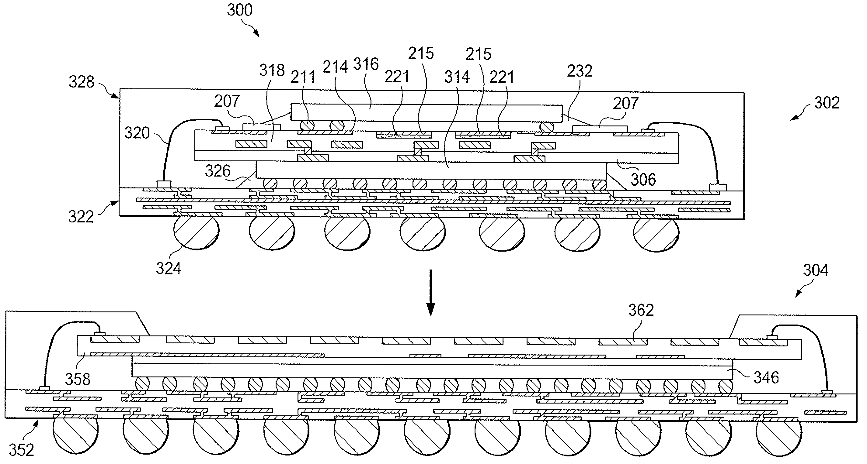
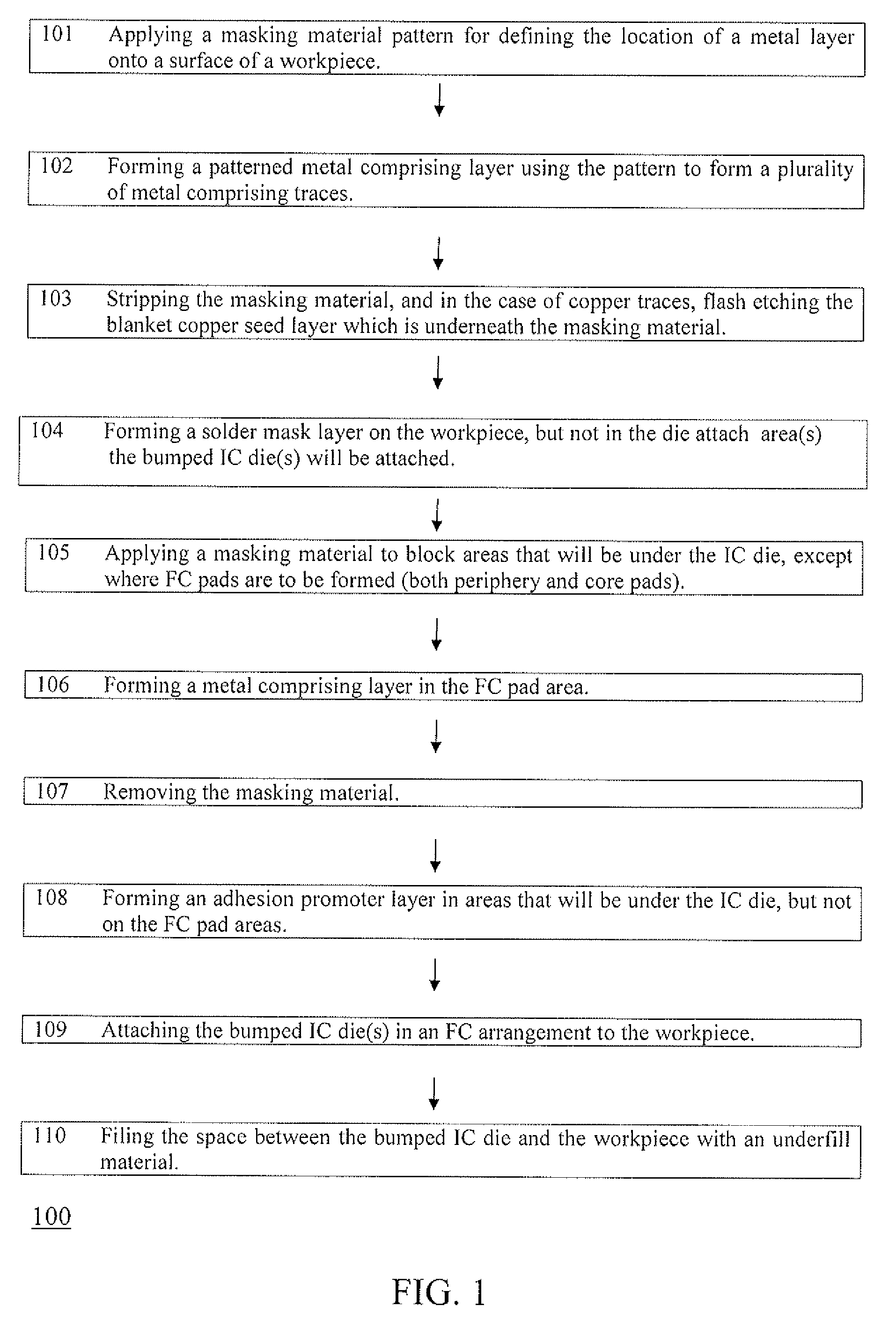
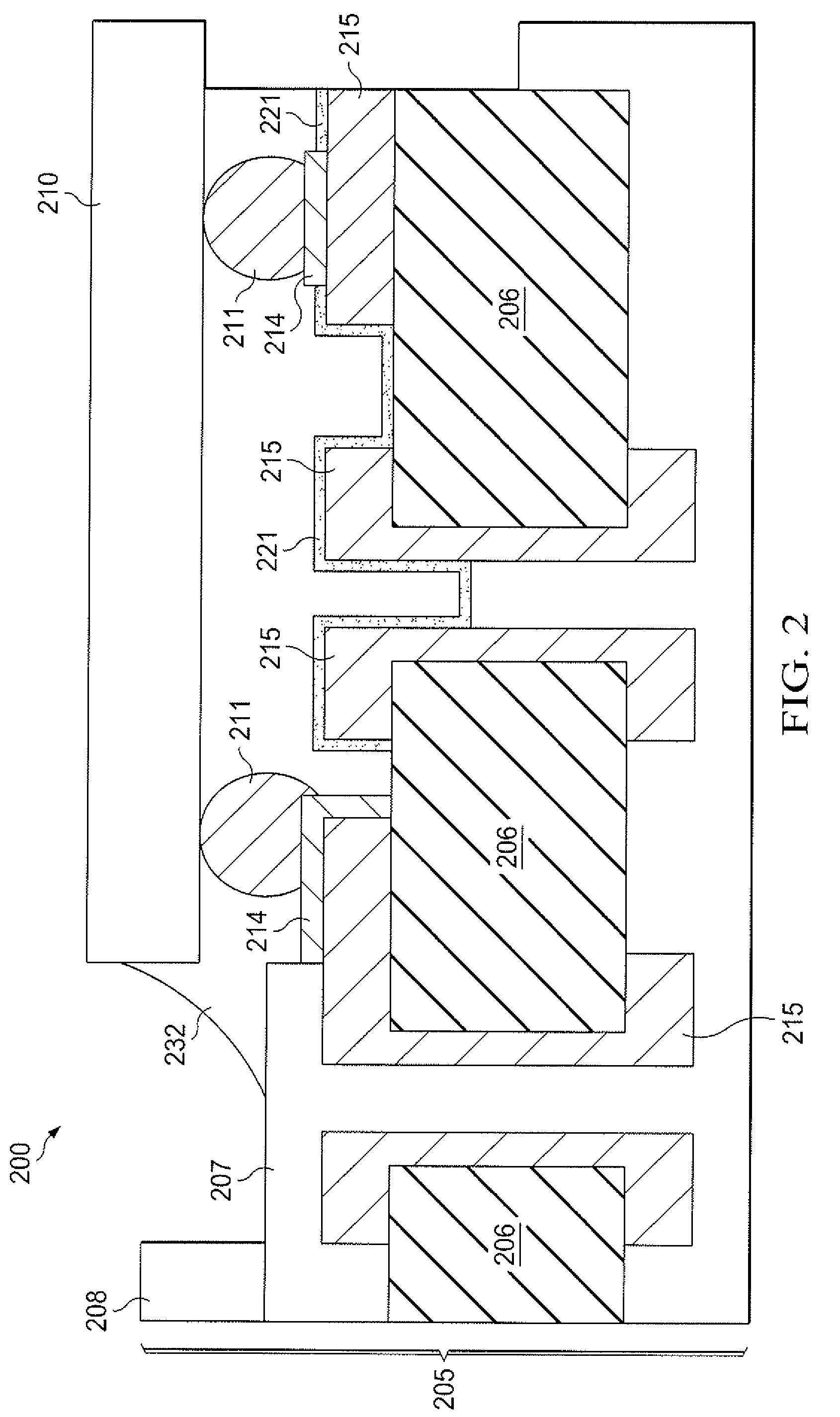
[0016]Some embodiments of the present invention include selectively forming the adhesive promoter layer on the workpiece surface in the die attach area, but not on the FC pads. The adhesive promoter layer has been found by the present Inventor to allow the solder mask layer to be absent in areas of the workpiece surface corresponding to areas beneath the bumped IC die, thus increasing the height of the gap between the IC die and the workpiece. The increased gap reduces the challenge of the underfill flow underneath the IC die, generally producing reduced underfill voids particular significant in tight areas including in the center of the package under the die, leading to improved reliability. Embodiments of the invention thus can effectively solve both the problem of the gap between the IC die and the workpiece being too small to properly underfill by removing the gap reducing thickness of the solder mask layer on the workpiece under the die, without the problems that generally arise without a solder mask layer including poor adhesion and uncontrolled oxidation (corrosion).

Problems solved by technology

In general, for the first and third PC bonding methods the gap distance between bottom surface of IC die and top of substrate is large enough to not generally have significant problems in properly underfilling the gap region.
Particularly in the case of FC Au—Au bonding technology, a very small gap results between the bottom of the die and the top of the substrate as a result of the Au stud collapse onto the EC pads on the substrate.
The presence of underfill material can make the flip-chip (FC) packaging system susceptible to interfacial failure.
The present inventor has also recognized that if the solder mask layer is removed, adhesion problems to the surface of the workpiece can result, particularly to copper or other oxidizable metal regions, primarily due uncontrolled oxidation (corrosion), such as from moisture in the ambient.
Particularly in the case of Au—Au bonding technology due to Au stud collapse to the Au stud bump on the bond pad on the workpiece during bonding, a very small gap between bottom of the IC die and top surface of workpiece results.
As the gap is reduced, the challenge of proper underfill flow underneath the IC die increases, generally producing underfill voids in tight areas concentrated mostly in the center of the package under the die, which can lead to reliability failures.
However, particularly when a solder masking layer is not present on the workpiece surface, the present Inventor has observed that the adhesion between the workpiece surface and the underfill can worsen.
For example, in the case of copper, without a solder mask layer on the surface of the copper interconnect, the copper can oxidize and result in poor adhesion and resulting delamination between the workpiece and the underfill.
In addition, in the case of a solder comprising layer on the FC pads, the solder comprising layer generally also remains unreacted by the selective formation processing.

Method used


Image

  • Flip chip semiconductor device having workpiece adhesion promoter layer for improved underfill adhesion
  • Flip chip semiconductor device having workpiece adhesion promoter layer for improved underfill adhesion
  • Flip chip semiconductor device having workpiece adhesion promoter layer for improved underfill adhesion

Examples


Embodiment Construction

[0021]The present invention is described with reference to the attached figures, wherein like reference numerals are used throughout the figures to designate similar or equivalent elements. The figures are not drawn to scale and they are provided merely to illustrate the instant invention. Several aspects of the invention are described below with reference to example applications for illustration. It should be understood that numerous specific details, relationships, and methods are set forth to provide a full understanding of the invention. One having ordinary skill in the relevant art, however, will readily recognize that the invention can be practiced without one or more of the specific details or with other methods. In other instances, well-known structures or operations are not shown in detail to avoid obscuring the invention.

[0022]The present invention is not limited by the illustrated ordering of acts or events, as some acts may occur in different orders and / or concurrently w...


PUM


Abstract

A semiconductor device assembly (200) includes a workpiece (205) having a surface including a die attach region corresponding to regions under an integrated circuit (IC) die 210. The die attach region of workpiece (205) includes non-noble metal surfaces (215) and a plurality of flip chip (FC) pads at pad locations (214). A solder mask layer (207) is on a surface of the workpiece (205) outside the die attach region. The non-noble metal surfaces (215) in the die attach region include an adhesion promoter layer (221), wherein the adhesion promoter layer (207) is absent from the plurality of FC pads (214). An integrated circuit (IC) die (210) having a plurality of bumps (211) bonded in a flip chip arrangement to the workpiece (205). An underfill material (232) fills a space between the bumped IC die (210) and the workpiece (205).

Description

FIELD OF THE INVENTION[0001]The present invention is related in general to the field of semiconductor devices and packaging of semiconductor devices, and more specifically to flip-chip (FC) package comprising devices having improved adhesion of underfill to a substrate surface.BACKGROUND[0002]The FC package is an advanced packaging technique for connecting an integrated circuit (IC) die to a substrate, such as printed circuit board (PCB). During the packaging process, the IC die is turned upside down to connect to the IC die to the metal bond pads on the substrate and hence the metal conductive wires of the substrate.[0003]The FC package generally comprises at least one substrate, a semiconductor die including a plurality of bumps, an underfill layer, and a plurality of solder balls. The substrate is commonly a dielectric material with two sides that have respectively a first metal interconnect layer including bond pads and a second metal interconnect layer. The first and the second...

Claims


Application Information

Patent Timeline
Patent Type & Authority Applications(United States)
IPC IPC(8): H01L21/50H01L23/48
CPCH01L21/563H01L2924/15311H01L23/498H01L23/49816H01L23/49827H01L24/16H01L24/81H01L25/105H01L2224/1134H01L2224/13144H01L2224/73203H01L2224/73204H01L2224/81205H01L2224/81801H01L2924/01078H01L2924/01079H01L2924/14H01L2924/1433H01L2924/1815H01L2224/16225H01L2224/32225H01L2924/19107H01L23/3128H01L2924/00H01L2924/00014H01L2924/00011H01L2224/0401
Inventor GALLEGOS, BERNARDO
Owner TEXAS INSTR INC
Why Eureka
Try Eureka