Audible noise suppression in a resonant switching power converter

Inactive Publication Date: 2010-01-28
CIRRUS LOGIC INC
View PDF103 Cites 55 Cited by
  • Summary
  • Abstract
  • Description
  • Claims
  • Application Information

AI Technical Summary

Benefits of technology

[0010]The resonant switching power converter includes a resonant tank circuit, a switching circuit for transferring energy to the resonant tank circuit from an input voltage source, and a transformer for coupling the resonant tank circuit to an output of the switching power converter. In a low-powe

Problems solved by technology

However, when low or zero-load conditions are encountered, the required switching frequency may become impractical and will typically cause a dramatic drop in efficiency due to increases in switching losses in conjunction with the relative drop in output power vs. the power consumed in ordinary

Method used


Image

  • Audible noise suppression in a resonant switching power converter
  • Audible noise suppression in a resonant switching power converter
  • Audible noise suppression in a resonant switching power converter

Examples


Embodiment Construction

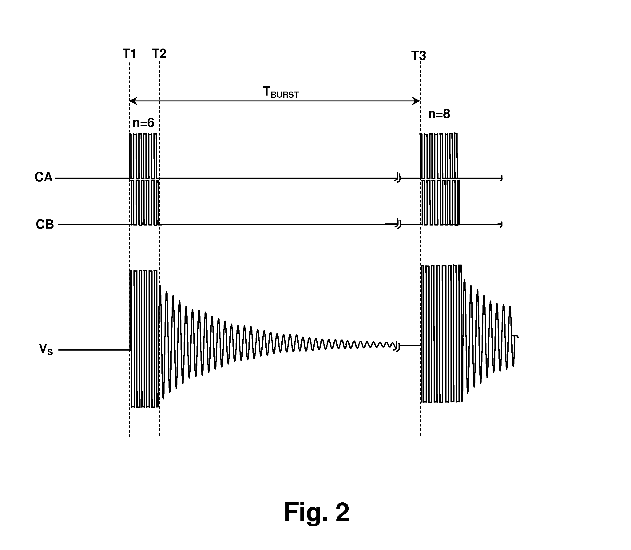
[0018]The present invention encompasses circuits and methods for reducing audible vibration in inductors and output transformers of resonant switching power converters operating in low power burst mode. Variations in the burst and / or pulse structure are made between bursts to widen the audio frequency spectrum of transients that cause the audible vibration.

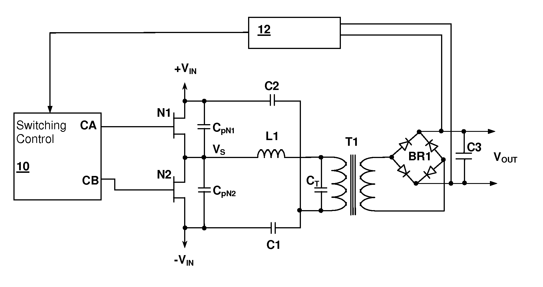
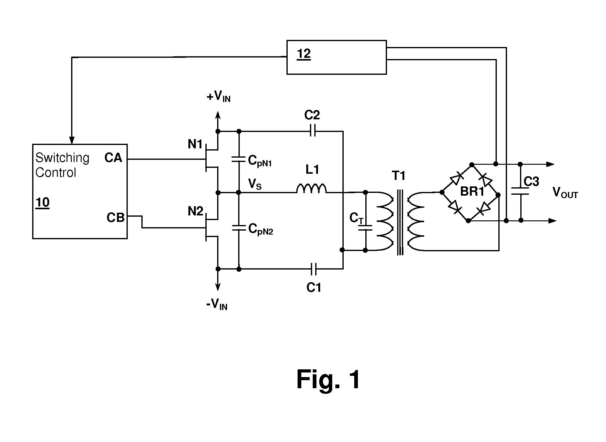
[0019]Referring now to FIG. 1, a resonant switching power converter circuit in accordance with an embodiment of the present invention is shown. A switching control circuit 10 controls a switching circuit implemented by transistors N1 and N2. A series-resonant tank circuit formed by an inductance and a capacitance and is energized by the switching action of transistors N1 and N2. A transformer T1 couples energy from the resonance tank circuit to a rectifier bridge BR1 which provides rectified current for charging output capacitor C3. Output voltage VOUT may be maintained at a predetermined voltage during burst mode by a feedback ci...


PUM


Abstract

Audible noise in resonant switching power converter during low-power burst mode operation is reduced by spreading the spectrum generated by the bursts, thereby reducing the amplitude of audio spectrum peaks in the current supplied through the resonant tank from a switching circuit. The spreading can be accomplished by varying the intervals between the bursts and/or by varying a pulse pattern within the bursts. The pulse pattern within the bursts can be varied by varying the number of pulses in the bursts, the polarity of the initial pulse of the bursts, and/or the duration of pulses within the bursts either uniformly or randomly. The burst pulse pattern may also be selected in alternation from a set of pulse patterns stored in a memory and the selection may be made randomly or systematically.

Description

[0001]This application Claims priority under 35 U.S.C. §119(e) to U.S. Provisional Patent Application Ser. No. 61 / 083,717 filed on Jul. 25, 2008.CROSS-REFERENCE TO RELATED APPLICATION[0002]The present U.S. Patent Application is related to U.S. patent application Ser. No. 12 / ______ entitled “RESONANT SWITCHING POWER CONVERTER WITH BURST MODE TRANSITION SHAPING”, filed contemporaneously herewith by the same inventor and assigned to the same Assignee. The disclosure of the above-referenced U.S. Patent Application is incorporated herein by reference.BACKGROUND OF THE INVENTION[0003]1. Field of the Invention[0004]The present invention relates generally to switching power regulator circuits, and more specifically, to a resonant switching power converter in which burst mode pulse patterns are varied between bursts.[0005]2. Background of the Invention[0006]In resonant switching power converters, as output current demand falls, the switching frequency is raised to reduce the power output. Ho...

Claims


Application Information

Patent Timeline
IPC IPC(8): H02M1/00
CPCH01F3/10H01F3/14H01F2038/026H01F38/08H01F38/02H02M1/42H02M1/0032Y02B70/10
Inventor MELANSON, JOHN L.
Owner CIRRUS LOGIC INC
Why Eureka
Try Eureka