

Wheel bearing device
- Summary
- Abstract
- Description
- Claims
- Application Information
AI Technical Summary
Benefits of technology
Problems solved by technology
Method used
Image

Examples
first embodiment
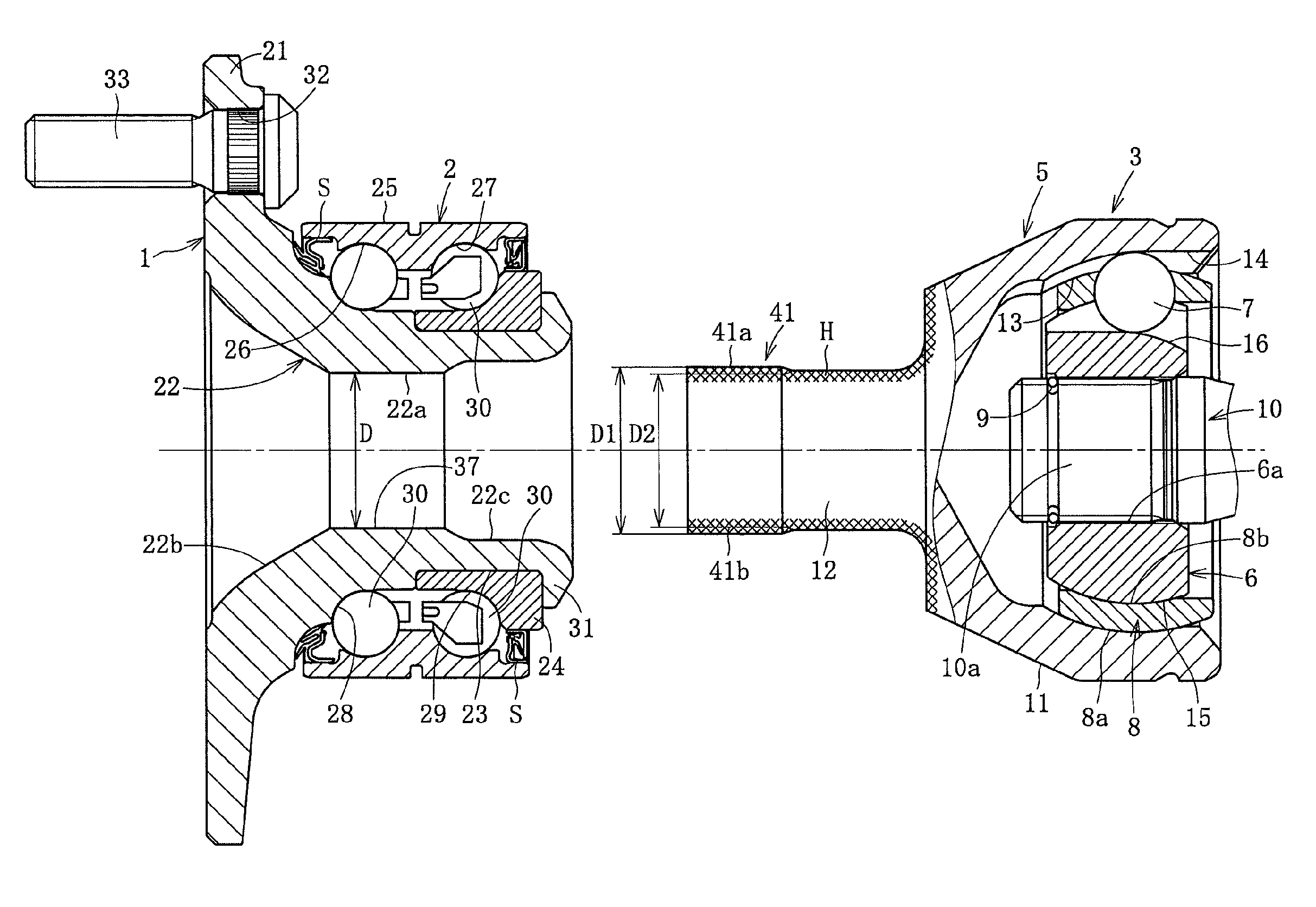
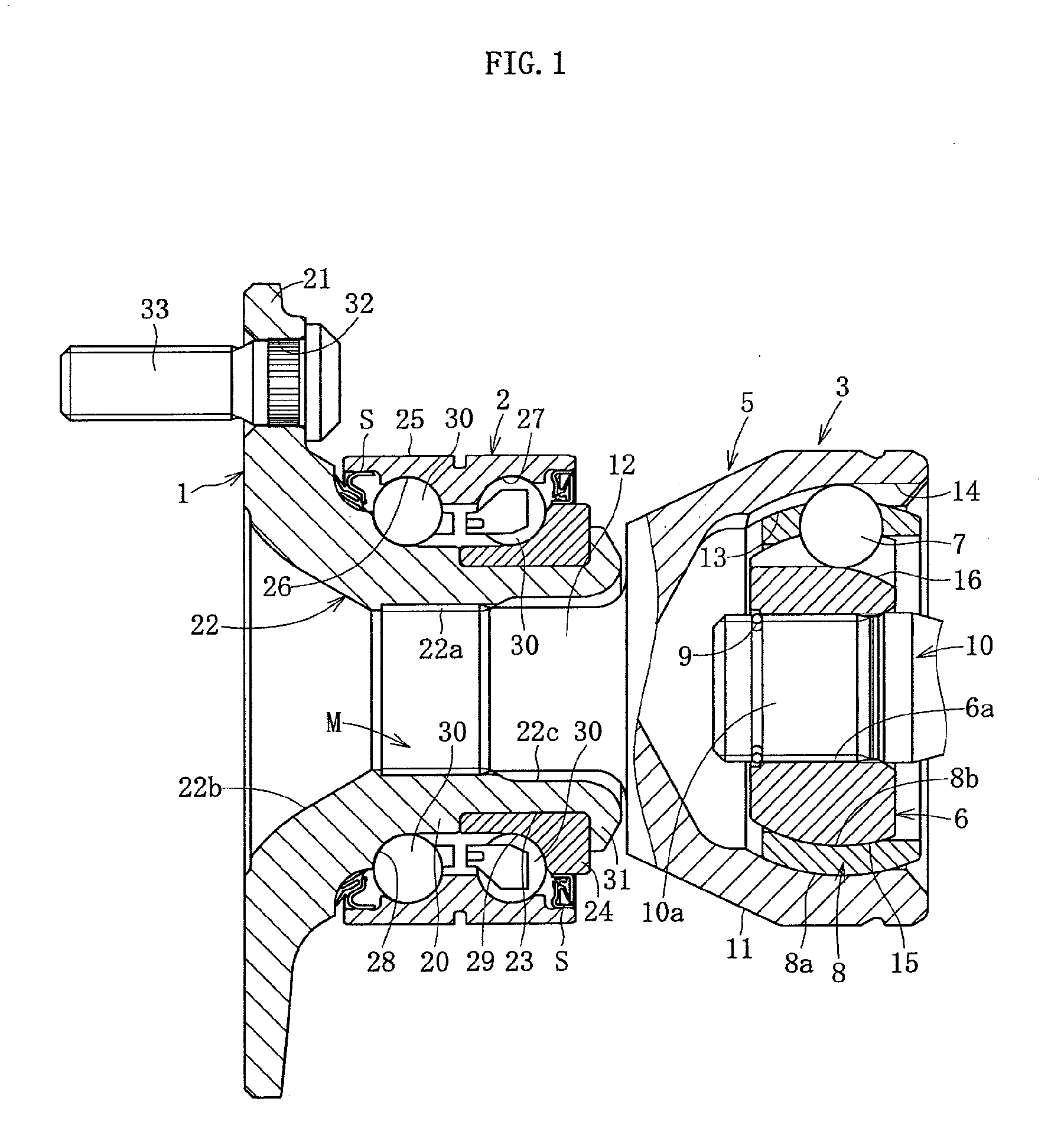
[0061]Embodiments of the present invention will be hereinafter described with reference to FIG. 1 to FIG. 12. FIG. 1 shows a wheel bearing device according to a In the wheel bearing device, a hub wheel 1, a double-row roller bearing 2, and a constant velocity universal joint 3 are integrated.
[0062]The constant velocity universal joint 3 includes an outer ring 5, an inner ring 6, a plurality of balls 7, and a cage 8 as main components. The outer ring 5 serves as an outer joint component. The inner ring 6 serves as an inner joint component disposed on an inner side of the outer ring 5. The balls 7 are interposed between the outer ring 5 and the inner ring 6, and transmit torque. The cage 8 is interposed between the outer ring 5 and the inner ring 6, and holds the balls 7. An end section 10a of a shaft 10 is press-fitted into a shaft hole inner diameter 6a of the inner ring 6, thereby connecting the inner ring 6 to the shaft 10 by spline engagement to allow torque transmission. A stop...
second embodiment
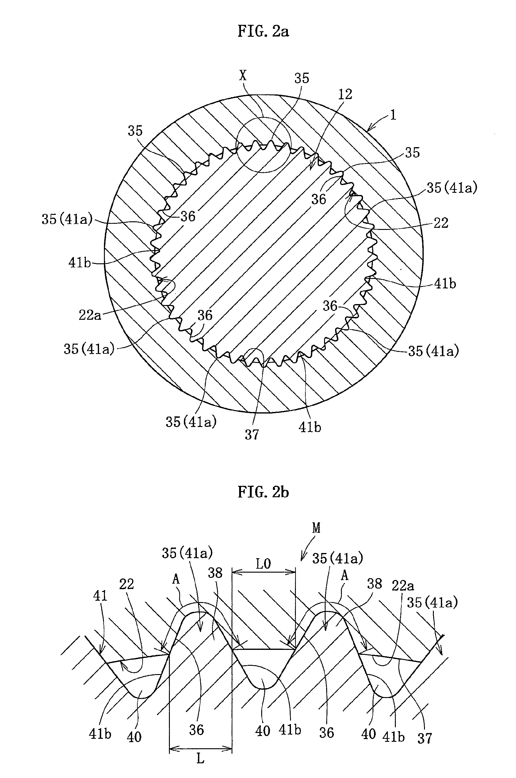
[0083]Here, when the stem shaft 12 of the outer ring 5 is press-fitted into the hub wheel 1, a protruding section 45, such as that shown in FIG. 5 is formed by a material being pushed out from the recesses 36 formed by the projections 35. The protruding section 45 is equivalent to an amount of material of a dimension of the recess 36 into which the recess mating area 38 of the projection 35 fits (engages). The protruding section 45 is configured by the material pushed out from the recess 36 that has been formed, a material cut away to form the recess 36, both the material that has been pushed out and the material that has been cut away, or the like.
[0084]Therefore, the wheel bearing device shown in FIG. 1 requires an operation to remove the protruding section 45 after the constant velocity universal joint is assembled to the hub wheel 1. According to the second embodiment shown in FIG. 5, a pocket section 50 for housing the protruding section 45 is provided on the stem shaft 12.
[00...
fourth embodiment
[0096]According to each embodiment, the spline 41 configuring the projections 35 is formed on the stem shaft 12 side. The hardening treatment is performed on the spline 41 of the stem shaft 12, and the inner diameter surface of the hub wheel 1 is unhardened (raw material). On the other hand, as shown in FIG. 10a and FIG. 10b a spline 61 (configured by projecting strips 61a and recessing strips 61b) on which the hardening treatment is performed can be formed on the inner diameter surface of the hole section 22 of the hub wheel 1. The hardening treatment is not performed on the stem shaft 12. The spline 61 can also be formed by various processing methods, such as a broaching process, a cutting process, a pressing process, and an extracting process, which are conventionally known means. Various types of heat treatment, such as high-frequency hardening, and carburizing and quenching, can be used for the thermally hardening process.
[0097]In this instance, the projection direction interm...
PUM
 Abstract
Description
Claims
Application Information