Structure And Method Of Solar Cell Efficiency Improvement By Strain Technology

a solar cell and strain technology, applied in the field of solar cell efficiency improvement, can solve the problems of increasing the price of fossil fuel, ineffective conversion efficiency improvement of amorphous silicon thin layer, and difficult cutting and manufacturing procedures of polycrystalline silicon than those of single crystalline silicon, etc., to achieve the effect of improving photoelectric conversion efficiency, and generating a tension in the solar cell

Inactive Publication Date: 2010-02-04
NAT TAIWAN UNIV
View PDF4 Cites 15 Cited by
  • Summary
  • Abstract
  • Description
  • Claims
  • Application Information

AI Technical Summary

Benefits of technology

[0008]In accordance with one aspect of the present invention, a method for improving photoelectric conversion efficiency in a solar cell is provided. The method includes a step being one selected from a group consisting of: (a) applying a mechanical stress to the solar cell; (b) generating a tension in the solar cell by

Problems solved by technology

Since fossil fuel, which is the material humans depend on to obtain energy, might be drained out in the twenty-first century, and leads to the increased price of fossil fuel.
Due to the mechanical properties of polycrystal, the cutting and manufacturing procedures of the polycrystalline silicon are more difficul

Method used


Image

  • Structure And Method Of Solar Cell Efficiency Improvement By Strain Technology
  • Structure And Method Of Solar Cell Efficiency Improvement By Strain Technology
  • Structure And Method Of Solar Cell Efficiency Improvement By Strain Technology

Examples


first embodiment

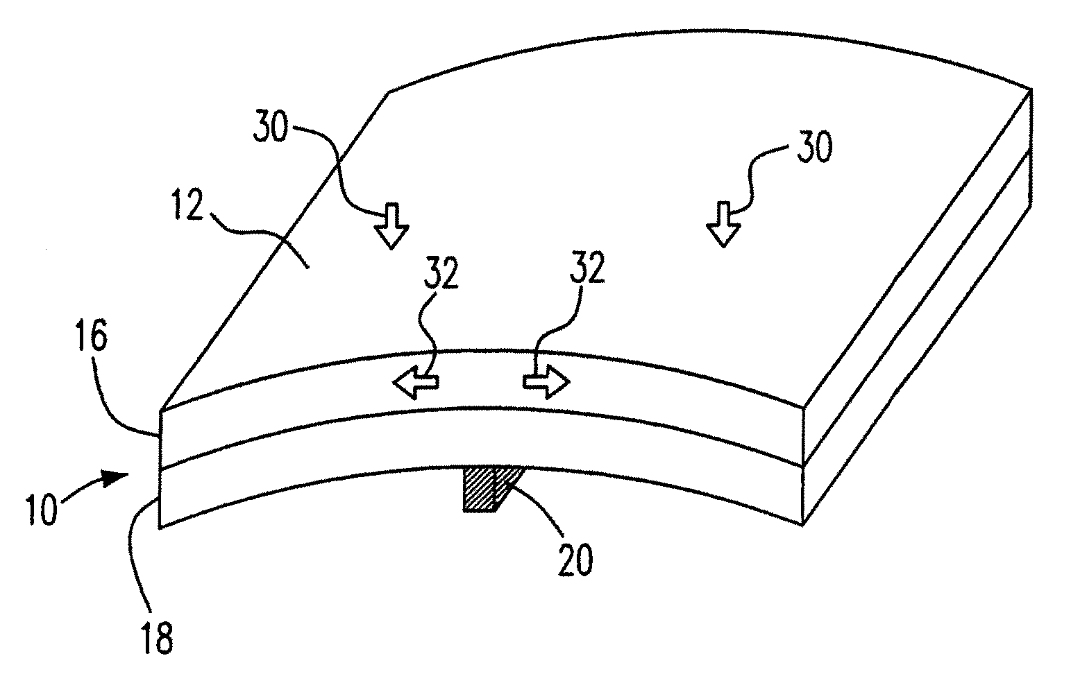
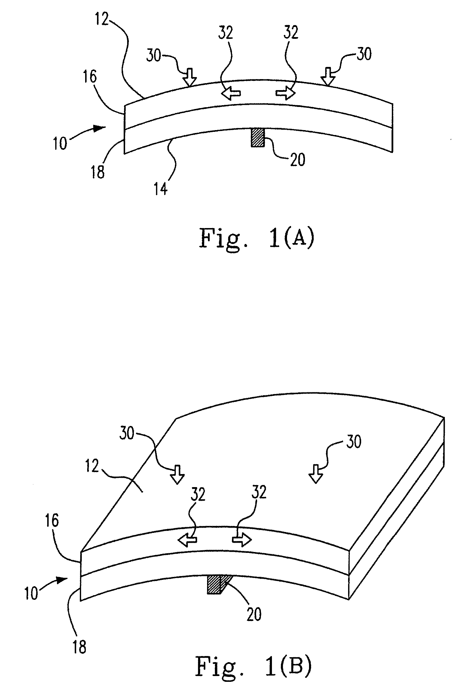
[0035]Please refer to FIGS. 1(A) and 1(B), which schematically illustrate the uniaxial tensile strain generated from the implemented uniaxial stress on the solar cell in accordance with the present invention. In FIGS. 1(A) and 1(B), the solar cell having a P-N junction structure is adapted. For the convenient illustration, the solar cell is divided into the upper part 16 and the lower part 18, and a gasket is disposed on the second surface 14. While a downward uniaxial stress 30 is applied on the different sides of the first surface 12 according to the gasket 20 as the axis, the gasket 20 actually provides an upward supporting force, and the uniaxial stress 30 and the support force do not excess the critical value of fragmentation of the solar cell 10.

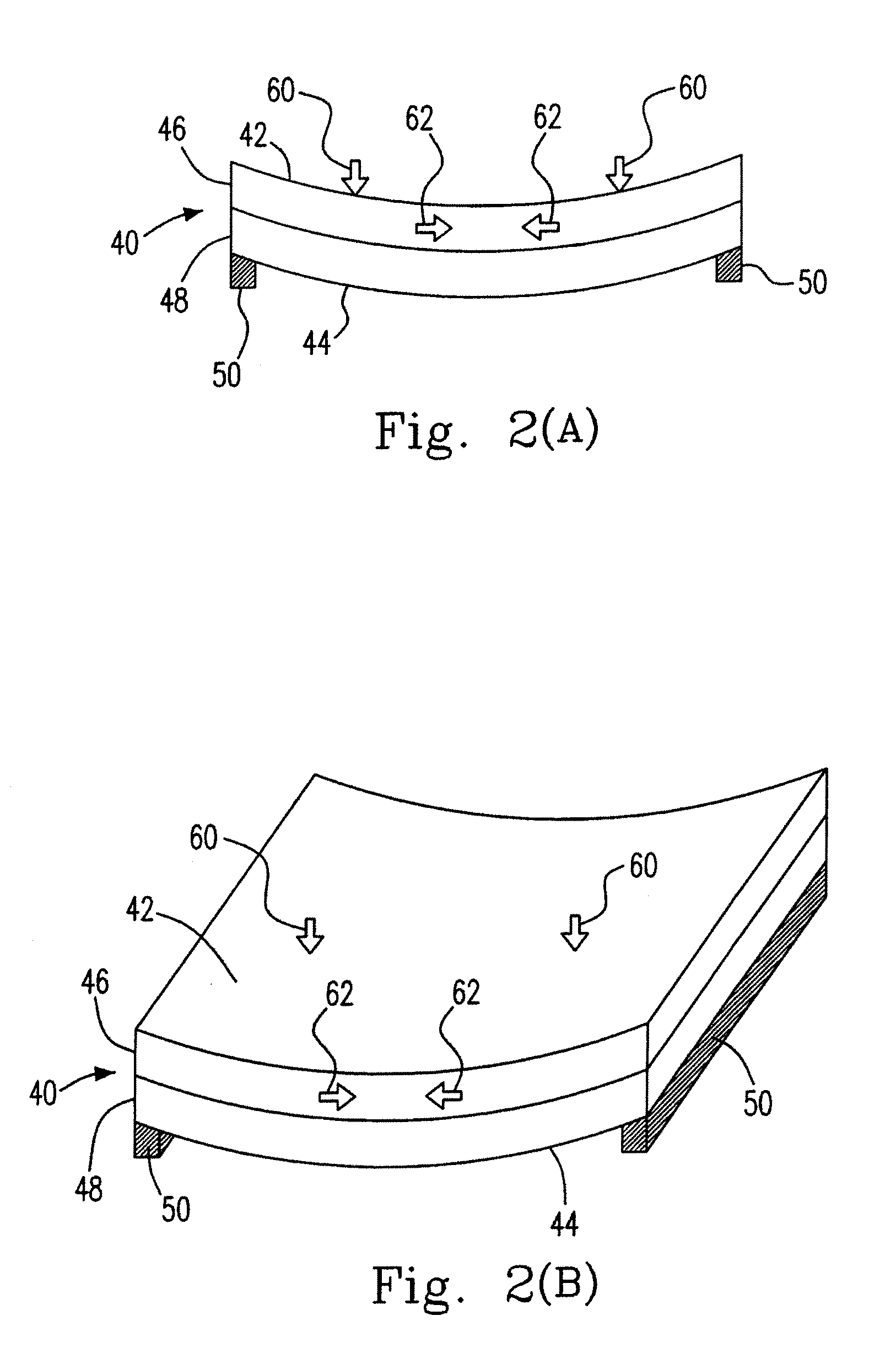
[0036]Please refer to FIGS. 2(A) and 2(B), which schematically illustrate the uniaxial compressive strain generated from the implemented uniaxial stress on the solar cell in accordance with a second embodiment of the present invention....

third embodiment

[0037]Please refer to FIGS. 3(A) and 3(B), which schematically illustrate the biaxial tensile strain generated from the implemented biaxial stress on the solar cell in accordance with the present invention. In FIGS. 3(A) and 3(B), it is assumed that the squared solar cell 70 with the P-N junction structure is provided, and 76 and 78 are denoted as the upper part and the lower part of the solar cell 70 respectively. The bar-shaped gasket is substituted for a cone-shaped gasket 80 to be mounted on the center of the second surface 74. The downward biaxial stresses 90 are implemented perpendicular on the distinct four corners of the first surface 72 of the solar cell 70, and the outwardly-radial tensile strains 92 which is centered by the cone-shaped gasket 80 are formed interior the upper part 76 of the solar cell 70. This tensile strain 92 also can be named as the biaxial tensile strain.

[0038]It is known that the gasket is not limited in the bar-shape, cone-shape, circular shape or ot...


PUM


Abstract

A structure and a method of the solar cell efficiency improvement by the strain technology are provided. The solar cell has a first surface and a second surfaces which at least a gasket is disposed thereon for supporting the solar cell and being the axle whiling stressing. The method includes the steps of: (a) applying at least a stress on the first surface; (b) generating a supporting force on the second surface; and (c) generating at least a strain in the solar cell. In addition, the present invention also includes a method involving a step of: (a) applying a mechanical stress to the solar cell; (b) generating a tension in the solar cell by at least two materials having different lattice constants; or (c) generating another tension in the solar cell by a shallow trench isolation filler, a high tensile/compressive stress silicon nitride layer and a combination thereof.

Description

FIELD OF THE INVENTION[0001]The present invention relates to a structure and a method of the solar cell efficiency improvement. In particular, the present invention relates to a structure and a method of the solar cell efficiency improvement by the strain technology.BACKGROUND OF THE INVENTION[0002]Since fossil fuel, which is the material humans depend on to obtain energy, might be drained out in the twenty-first century, and leads to the increased price of fossil fuel. Therefore, every country takes efforts on developing new energy resources in the recent years, including solar energy, wind power, water power, biomass power and newly-explored fossil fuel storage sources, etc. Among these, solar energy which is radiated from the sun is deemed as the clear energy without generating greenhouse gases or aggravating the greenhouse effect, and has great benefit on resolving the energy requirement and decreasing carbon dioxide emission.[0003]The present solar cells apply various materials...

Claims


Application Information

Patent Timeline
IPC IPC(8): H01L31/00H01L21/02
CPCH01L31/0248Y02E10/50H01L31/04H01L31/0264
Inventor TSAI, JYUN-JHEYANG, YING-JHELIU, CHEE WEE
Owner NAT TAIWAN UNIV
Why Eureka
Try Eureka