Micro-gripper
- Summary
- Abstract
- Description
- Claims
- Application Information
AI Technical Summary
Benefits of technology
Problems solved by technology
Method used
Image
Examples
Embodiment Construction
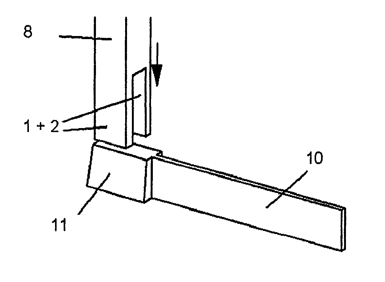
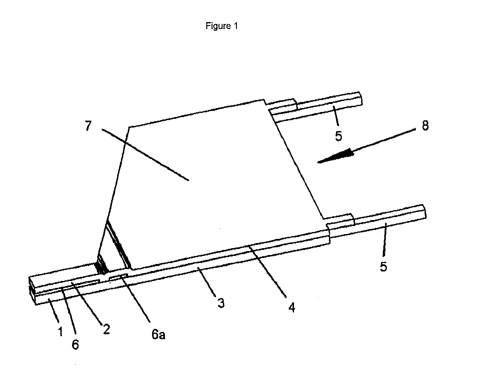
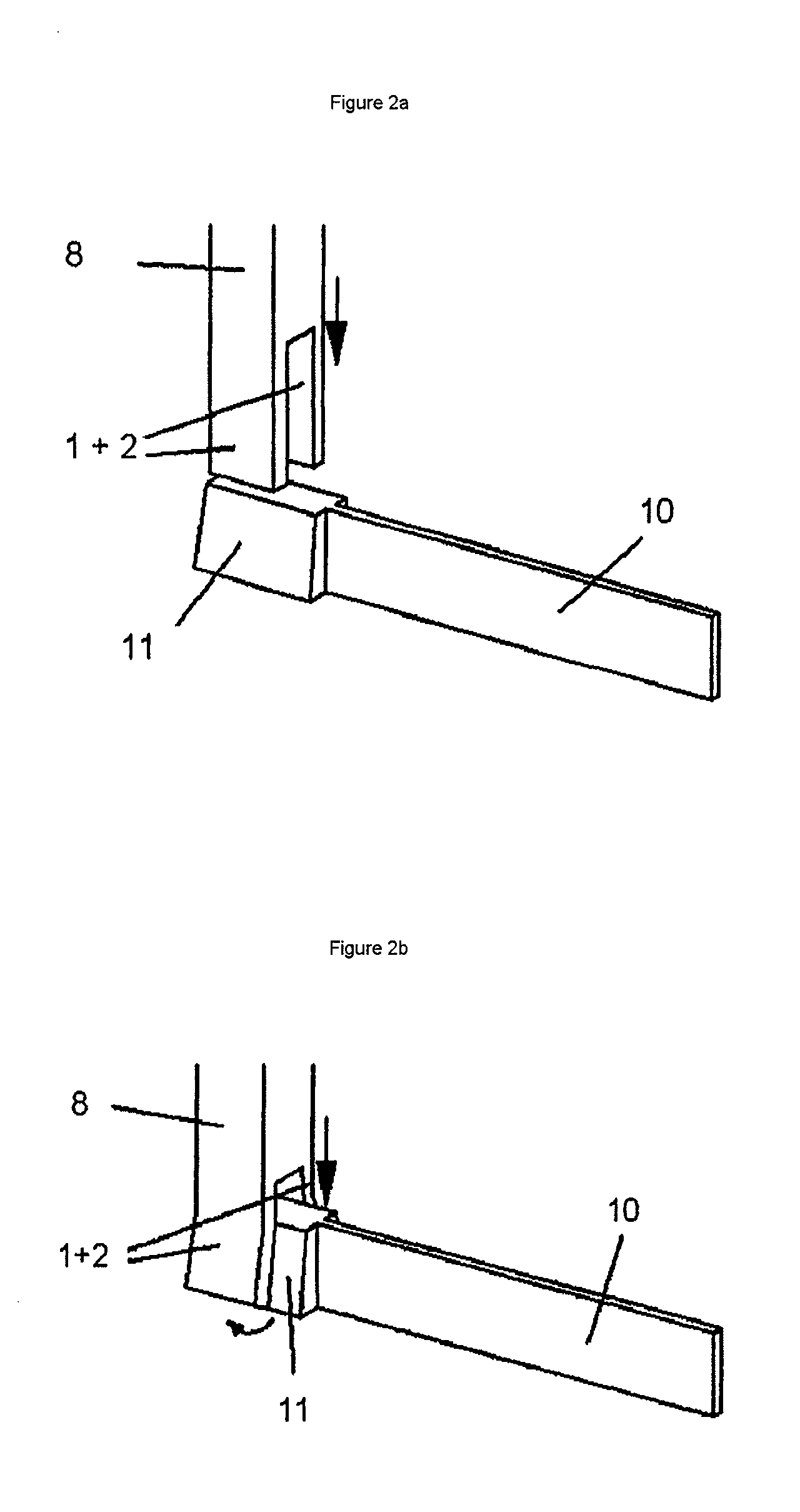
[0042]FIG. 1 shows a perspective view of a micro-gripper 8 produced according to the invention, which is implemented as a planar body. The planar body 8 comprises a first material layer 3 and a second material layer 4, which is bonded to the first material layer 3. The planar body 8 may be divided into a base body area having the associated planar body surface part 7 and a gripping body area having the gripping elements 1 and 2, between which the receptacle slot 6 is located. Furthermore, a continuous gap 6a running transversely to the gripping elements 1, 2 is provided in the connection area between base body and gripping body in the micro-gripper 8 shown. This gap is used for improved introduction of forces which arise by an elastic deformation of the gripping elements 1, 2 into the material layers 3 and 4. Thin webs 5 are provided on the right side of the micro-gripper 8 shown for fastening the micro-gripper on the substrate 9. The background for this is that during the etching p...
PUM
| Property | Measurement | Unit |
|---|---|---|
| Length | aaaaa | aaaaa |
| Length | aaaaa | aaaaa |
| Radius | aaaaa | aaaaa |
Abstract
Description
Claims
Application Information
 - R&D
- Intellectual Property
- Life Sciences
- Materials
- Tech Scout
- Unparalleled Data Quality
- Higher Quality Content
- 60% Fewer Hallucinations
Browse by: Latest US Patents, China's latest patents, Technical Efficacy Thesaurus, Application Domain, Technology Topic, Popular Technical Reports.
© 2025 PatSnap. All rights reserved.Legal|Privacy policy|Modern Slavery Act Transparency Statement|Sitemap|About US| Contact US: help@patsnap.com


