Tube shields having a thermal protective layer

a technology of thermal protective layer and tube shield, which is applied in the direction of corrosion prevention, steam boiler components, metal-working apparatuses, etc., can solve the problems of high corrosive environment, high corrosive environment, and high temperature exposure of boiler tubes employed in combustion chambers, so as to reduce maintenance costs, prolong effective repair and replacement cycles, and reduce overall cost of utility

Inactive Publication Date: 2010-02-18
WESSEX
View PDF14 Cites 25 Cited by
  • Summary
  • Abstract
  • Description
  • Claims
  • Application Information

AI Technical Summary

Benefits of technology

[0023]An aspect of the present invention is to extend the effective repair and replacement cycles of the heat exchangers and combustion chambers, especially tubes and tube shields. The overall cost of the utility is reduced by the concomitant reduction in maintenance costs.
[0024]The present invention extends the effective lifespan of conventional tube shields and tubes. Furthermore, it reduces down time and repair costs.
[0025]An aspect of the present invention is to reduce the overall costs of operating heat exchangers or combustion chambers. Cost savings are found in the materials for replacing the damaged tubes and tube shields, in the reduction of employee work load needed to replace the tubes and tube shields, and in reduced facility downtime and economic loss.

Problems solved by technology

Condenser tubes may be used to convert gasses to liquids, such as steam to water for recycling back into a boiler, and may also be exposed to extreme temperatures.
The environment within the combustion chamber can be extremely corrosive and abrasive.
The boiler tubes employed in the combustion chamber are commonly exposed to highly abrasive and corrosive environments.
Exposure of the tubes to such environments often causes premature failure resulting in expensive maintenance and mounting boiler / facility downtime costs.
It is also known that with boiler tubes of a refuse or solid waste incinerator-type boiler, the heat-conductive performance deteriorates when soot and slag attach to the tubes requiring cleaning, and acids generated by combustion corrode the tubes, which results in deterioration of the tubes and ultimate failure.
In any case, exposed boiler tubes are subject to failure due to the hostile environment of the combustion chamber, and must be replaced frequently,
These tube shields are typically used in an effort to reduce and delay corrosion and erosion which results in eventual failure of the boiler tubes.
However, since such tube shields are readily corroded themselves with corrosive gases contained in exhaust gases, the tube shields themselves have durability of less than one year in the most hostile environments, and at worse they are corroded or eroded beyond useful life in less than three (3) months.
While conventional tube shields are designed to increase the life of the boiler tubes, they are still subject to destruction due to the corrosive environment, and must be replaced regularly.
These eddy currents increase wear, because the stream is not moving in laminar flow, as well as effecting combustion dynamics, emissions, and chemical byproducts.
Boiler tubes, and tube shields, exposed to this environment are corroded and eroded by the flow.
The high cost of energy has led society to extract usable heat from high thermal value waste streams.

Method used


Image

  • Tube shields having a thermal protective layer
  • Tube shields having a thermal protective layer
  • Tube shields having a thermal protective layer

Examples


Embodiment Construction

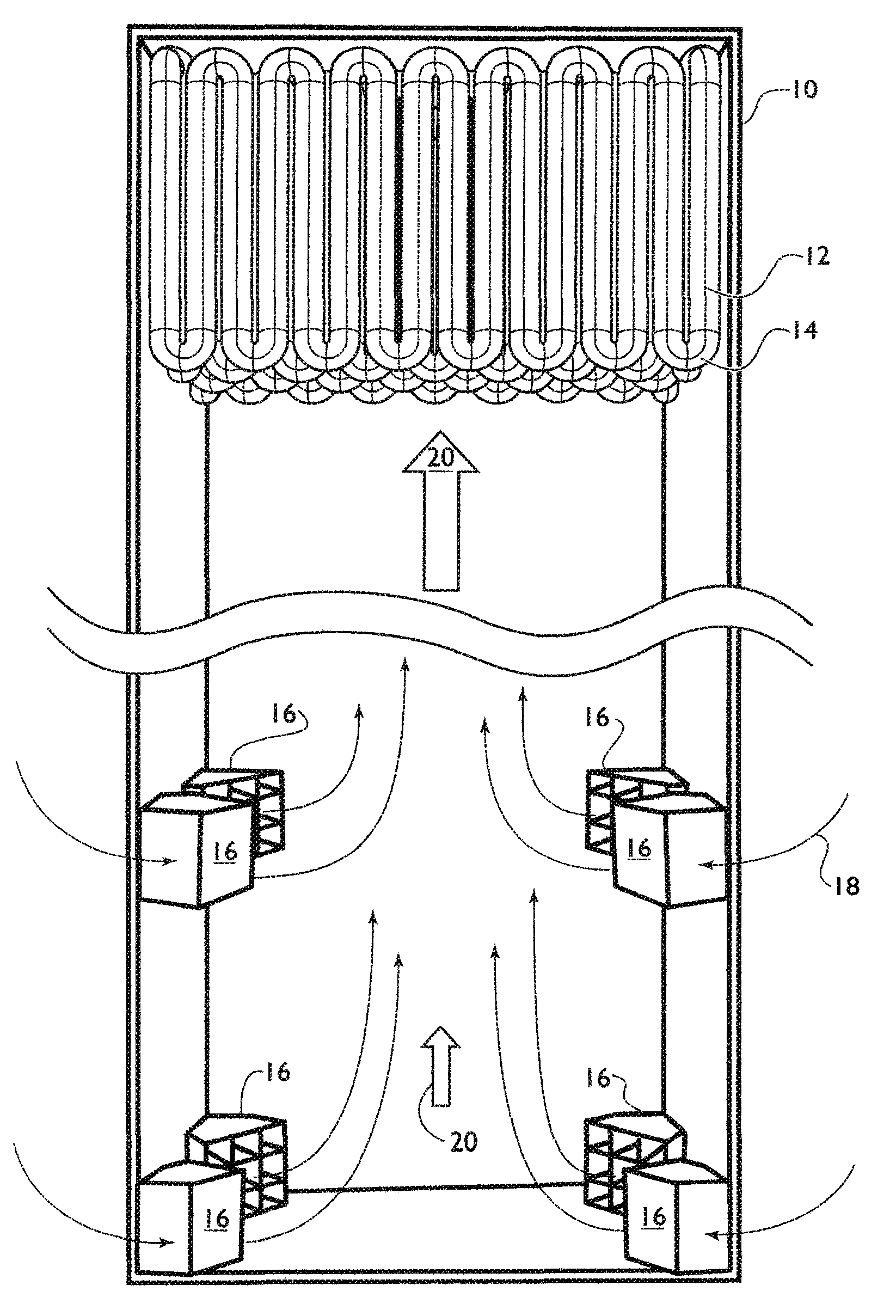
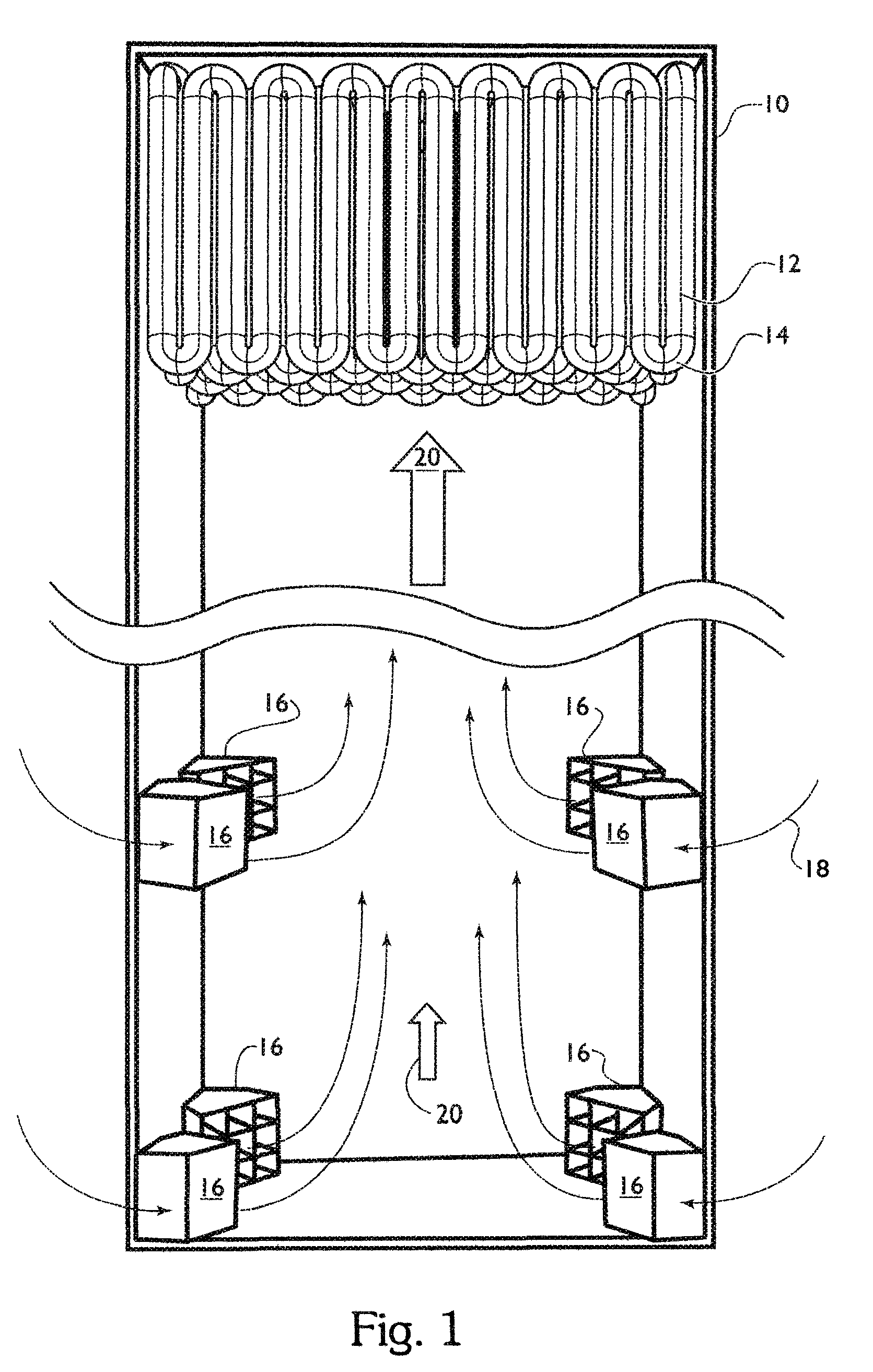
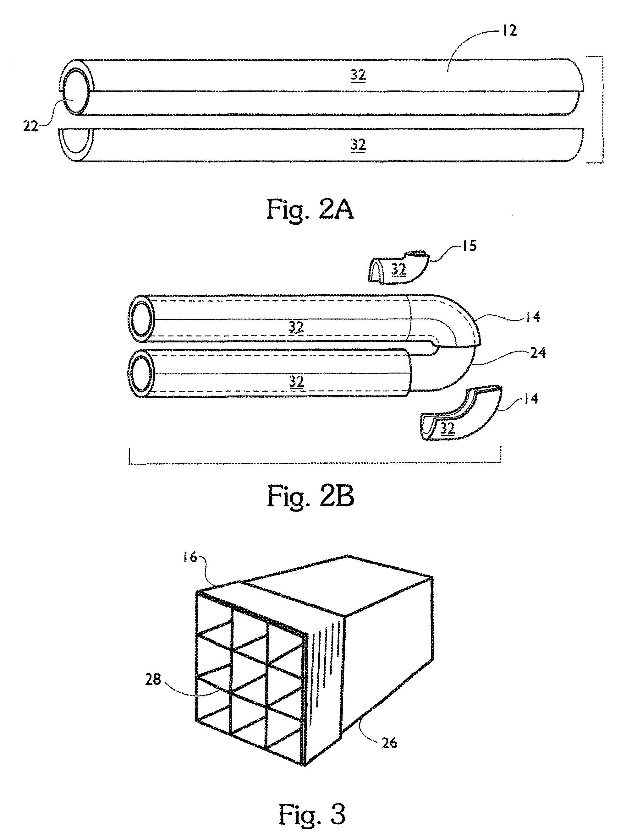
[0041]The present invention is described herein in light of a tangentially fired coal-burning furnace utilizing half shell tube shields 12, graphically represented in FIGS. 1, 2A, 2B, 4A, 4B, 5A, 5B, 5C, and 7 by example only, and is not limited to such a furnace and tube shield 12 designs, or applications. In a tangentially fired furnace, burner tips 16, shown in FIG. 3, may be located at each corner of a combustion chamber 10 having a square-shaped floor / ceiling. The axis of each burner tip 16 may be offset with respect to a central axis of the combustion chamber 10 and extend generally tangent to an imaginary cylinder, which defines a combustion zone 20, as shown in FIG. 1, where a fireball is generated during operation of the burner tips 16. Burner tips 16 are also customarily referred to simply as “burners”. Tangentially fired furnaces are used to heat many utility boilers, especially for the generation of energy from fossil fuel sources such as coal, propane, oil, petroleum, n...


PUM

PropertyMeasurementUnit
emissivityaaaaaaaaaa

Abstract

A tube shield, and method of manufacturing the tube shield, having a support structure with an external surface, an internal surface, and an edge, and a thermal protective layer on at least one surface of the shield support structure. The thermal protective layer is composed of a filler, one or more emissivity agent, and either an inorganic adhesive or a binder that is colloidal silica, colloidal alumina, or combinations thereof. A colorant, a surfactant, and / or a stabilizer may be incorporated into the thermal protective layer.

Description

BACKGROUND OF THE INVENTION[0001]Tube shields are found in furnaces, boilers, burners, heat exchangers, incinerators, and the like, and function to protect boiler / condenser tubes used in the generation of power, steam, condensation, heat, and the like, for a variety of applications including power generation, manufacturing and production processes, such as found in the petrochemical industries. Boiler tubes carry air, water, steam or other fluid. Condenser tubes also carry fluids in the form of gasses and liquids. Boiler tubes are exposed to an extreme heat source in a combustion chamber. Condenser tubes may be used to convert gasses to liquids, such as steam to water for recycling back into a boiler, and may also be exposed to extreme temperatures. Hot air, and / or ignited fuel, is dispensed through burner tips into the combustion chamber from external fuel sources such as coal, natural gas, biomass, slag, and the like. Under these general circumstances the mixture of fuels is eject...

Claims


Application Information

Patent Timeline
Patent Type & Authority Applications(United States)
IPC IPC(8): F28F9/00B21D53/02
CPCF22B37/107Y10T29/4935F28F19/002
Inventor OLVER, JOHN W.SIMMONS, JASON ANDREW
Owner WESSEX
Why Eureka
Try Eureka