Integrated Fan Drive System For Cooling Tower

a technology of integrated fan drive and cooling tower, which is applied in the direction of trickle cooler, field or armature current control, combustion air/fuel air treatment, etc., can solve the problems of unstable and dangerous operating conditions, immediate shut down of processing units, and petroleum refining cannot take place without cooling towers

Active Publication Date: 2010-02-25
PRIME DATUM
View PDF13 Cites 20 Cited by
  • Summary
  • Abstract
  • Description
  • Claims
  • Application Information

AI Technical Summary

Benefits of technology

[0011]Accordingly, it is an object of the present invention to provide a fan drive system that substantially eliminates the aforementioned problems and disadvantages associated with prior art gearbox-type fan drive systems.

Problems solved by technology

Refining of petroleum cannot take place without cooling towers.
The loss of cooling water circulation within a refinery can lead to unstable and dangerous operating conditions requiring an immediate shut down of processing units.
In addition, these processes have tapped a great deal of the cooling capacity reserve in the towers leaving some refineries “cooling limited” on hot days and even bottlenecked.
The duty cycle required of the fan drive system in a cooling tower environment is extreme due to intense humidity and icing conditions, wind shear forces, corrosive water treatment chemicals, and demanding mechanical drive requirements.
This prior art fan drive system is subject to frequent outages, a less-than-desirable MTBF (Mean Time Between Failure), and requires diligent maintenance, such as regular oil changes, in order to operate effectively.
Furthermore, prior art gearboxes typically require a separate gear to reverse the rotational direction.
Although this particular prior art fan drive system may have an attractive initial cost, cooling tower end-users found it necessary to purchase additional components such as composite gearbox shafts and couplings in order to prevent breakage of the fan drive components.
Thus, the life cycle cost of the prior art mechanical fan drive system compared to its initial purchase price is not equitable.
Thus, if there is a shutdown of the mechanical fan drive system associated with a particular cell, then that cell suffers a “cell outage”.
A cell outage will result in a decrease in the production of refined petroleum.
For example, a “cell outage” lasting for only one day can result in the loss of thousands of refined barrels of petroleum.
If numerous cells experience outages lasting more than one day, the production efficiency of the refinery can be significantly degraded.
The loss in productivity over a period of time due to the inefficiency of the prior art mechanical fan drive systems can be measured as a percent loss in total tower-cooling potential.
As more cell outages occur within a given time frame, the percent loss in total tower-cooling potential will increase.
This, in turn, will decrease product output and profitability of the refinery and cause an increase in the cost of the refined product to the end user.
It is not uncommon for decreases in the output of petroleum refineries, even if slight, to cause an increase in the price-per-barrel of petroleum and hence, an increase in the cost of gasoline to consumers.
Other types of prior art fan drive systems, such as V-belt drive systems, also exhibit many problems with respect to maintenance, MTBF and performance and do not overcome or eliminate the problems associated with the prior art gearbox-type fan drive systems.

Method used


Image

  • Integrated Fan Drive System For Cooling Tower
  • Integrated Fan Drive System For Cooling Tower
  • Integrated Fan Drive System For Cooling Tower

Examples


Embodiment Construction

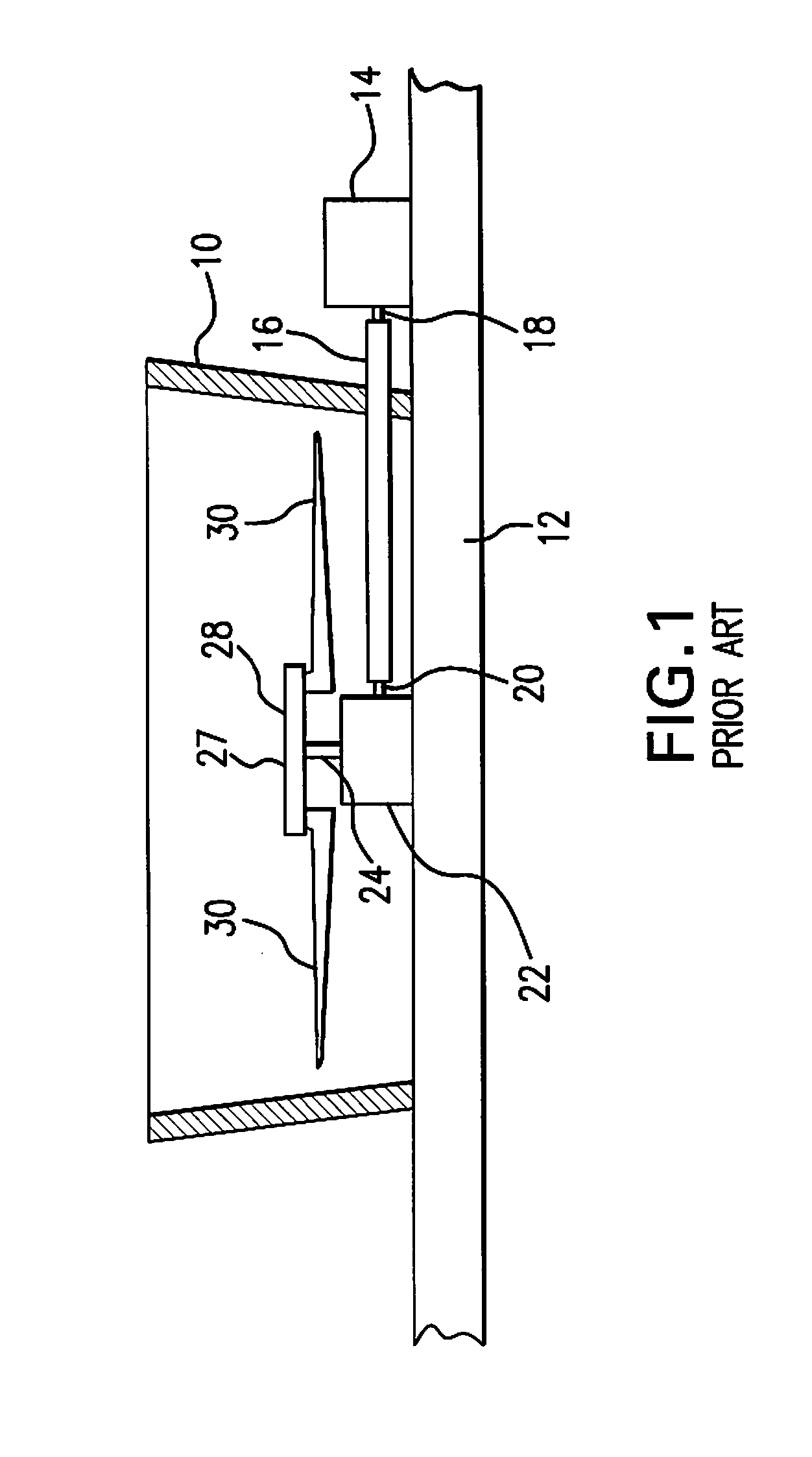
[0022]Referring to FIG. 1, there is shown a prior art mechanical fan drive system, and a portion of a wet cooling tower. The remaining portion of the wet cooling tower is not shown since the structure and operation of cooling towers is well known in the art. Fan cylinder or plenum 10 is positioned upon fan deck 12 of the cooling tower. The prior art mechanical fan drive system comprises an induction motor 14, drive shaft 16, couplings 18 and 20, and right-angle gearbox 22. Motor 14 is seated upon and / or secured to fan deck 12. Gearbox or gear reducer 22 is mounted to or supported by fan deck 12. Gearbox 22 has a vertical shaft 24 that rotates upon rotation of drive shaft 16. As shown in FIG. 1, fan 27 is located within fan cylinder 10 and comprises hub 28 and fan blades 30 that are attached to hub 28. Vertical shaft 24 is connected to fan hub 28. Thus, rotation of vertical shaft 24 causes rotation of fan hub 28 and fan blades 30.

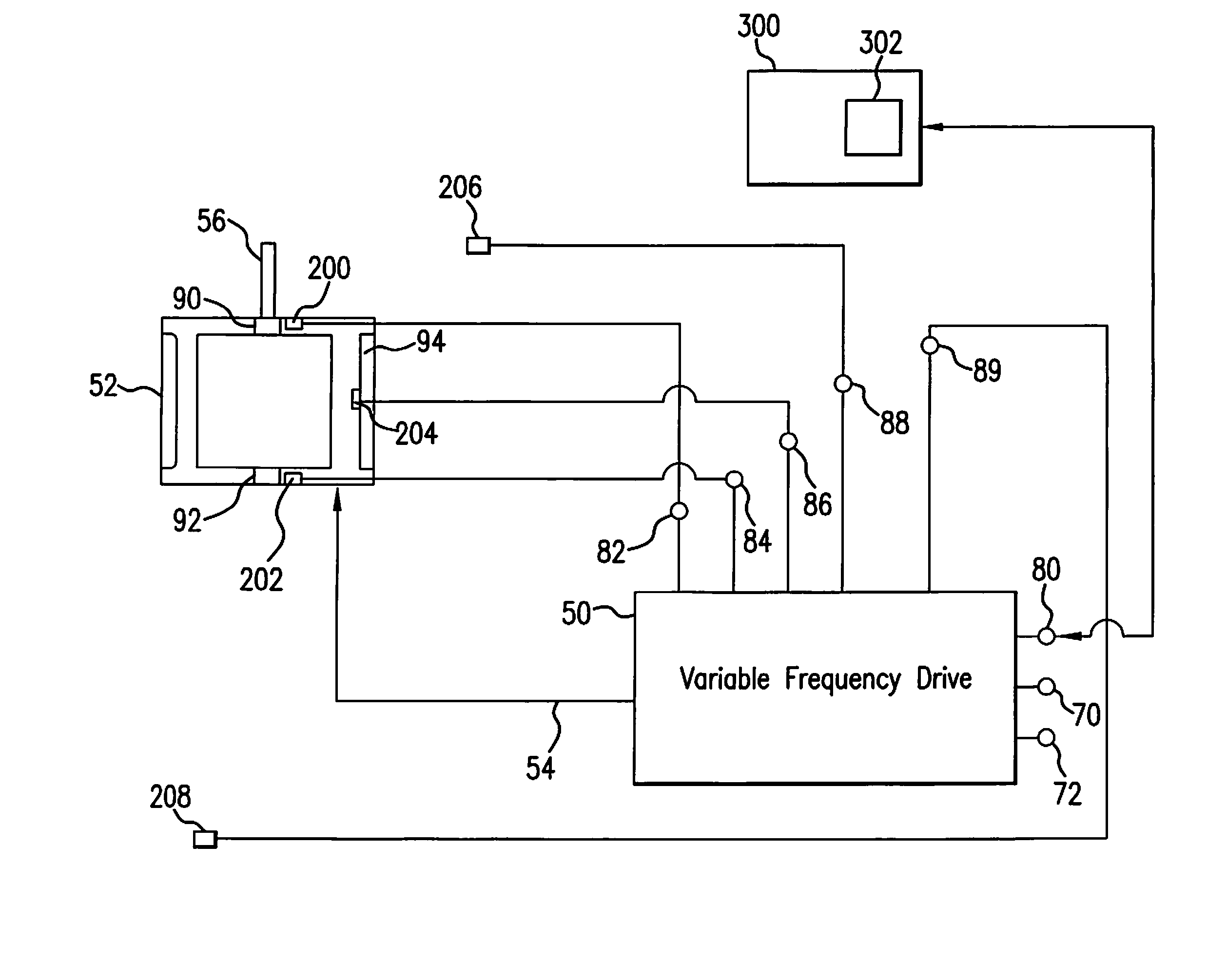
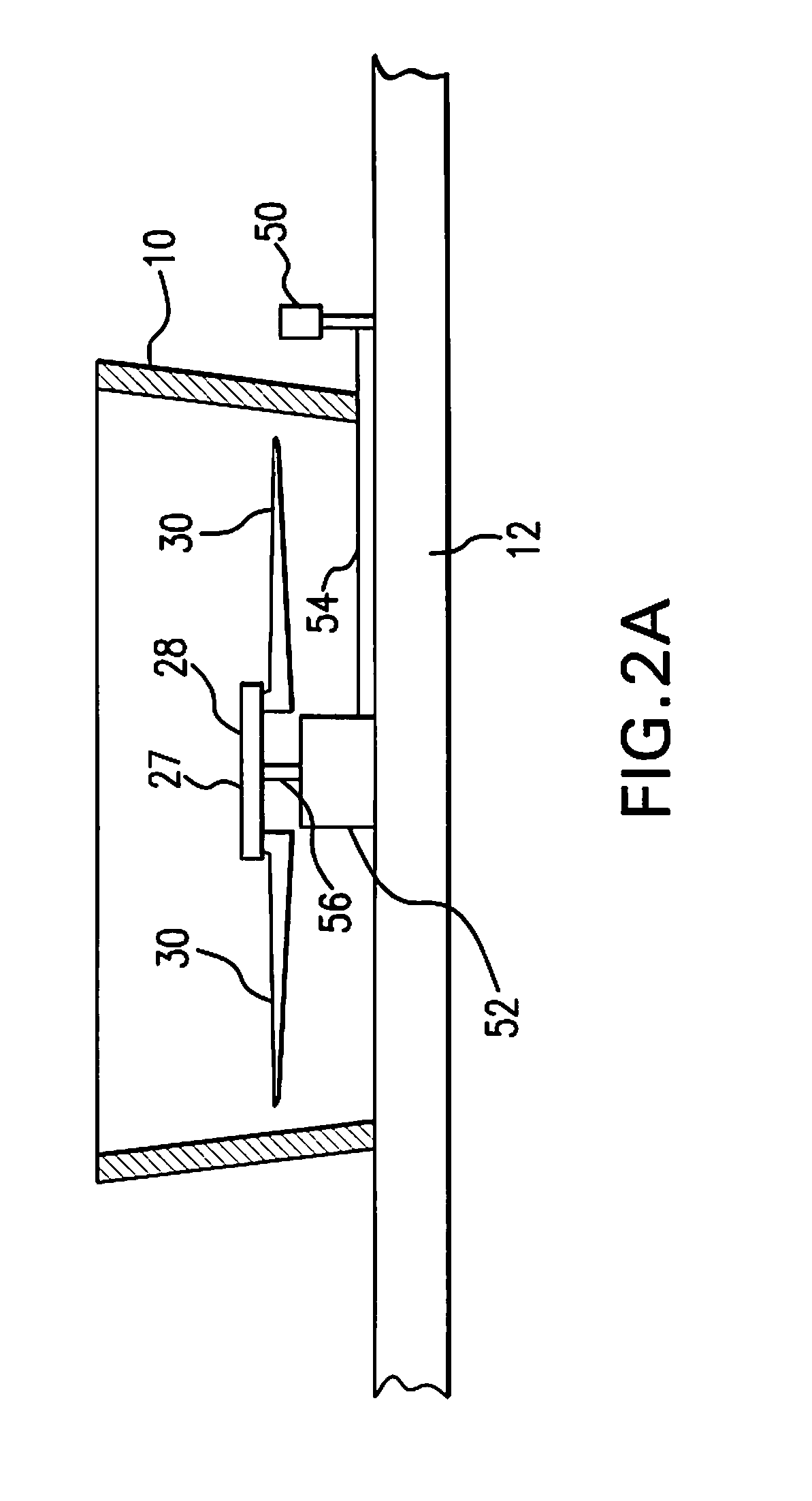
[0023]Referring to FIG. 2A, there is shown the fan dri...


PUM

PropertyMeasurementUnit
rotational speedaaaaaaaaaa
torqueaaaaaaaaaa
speedaaaaaaaaaa

Abstract

An integrated fan drive system for a cooling tower comprising a high-torque, low speed permanent magnet motor having a rotatable shaft, a fan comprising a hub that is directly connected to the rotatable shaft and a plurality of fan blades that are attached to the hub, and a variable frequency drive device in electrical signal communication with the permanent magnet motor to control the rotational speed of the permanent magnet motor. The high-torque, permanent magnet motor comprises no more than two bearings in operative association with the shaft. The variable frequency drive device has a variable frequency controller that has an input for receiving AC power and an output for providing electrical signals that control the operational speed of high-torque, permanent magnet motor. The variable frequency drive device also includes a user interface in electronic data signal communication with the variable frequency controller to allow a user to input motor speed control data.

Description

CROSS-REFERENCE TO RELATED APPLICATIONS:[0001]This application claims the benefit of U.S. Provisional Application No. 60 / 978,916, filed Oct. 10, 2007. The entire disclosure of the aforesaid application No. 60 / 978,916 is hereby incorporated by reference.TECHNICAL FIELD[0002]The present invention generally relates to a fan drive system for a wet cooling tower.BACKGROUND ART[0003]Wet cooling towers are well known in the art and are used in a variety of industries for cooling fluids such as water. The primary use of large, industrial cooling tower systems is to remove the heat absorbed in circulating cooling water systems used in power plants, petroleum refineries, petrochemical and chemical plants, natural gas processing plants and other industrial facilities. The absorbed heat is rejected to the atmosphere by the evaporation of some of the cooling water in mechanical forced-draft or induced draft towers.[0004]Cooling towers are widely used in the petroleum refining industry. Refining ...

Claims


Application Information

Patent Timeline
Patent Type & Authority Applications(United States)
IPC IPC(8): H02P27/04A61B1/00A61B17/00A61B17/04A61B17/06A61B17/28G01M1/38G05D7/00H04N7/18
CPCF04D19/00F04D27/004F28F25/10F28F27/003H02P6/001Y10T29/49245Y02B30/748F28F2250/08A61B17/0485Y10S261/11F04D29/668H02P29/0044F04D25/0606F05B2270/101H02P6/34H02P29/60Y02B30/70F04D25/06F28C1/00H02P27/06
Inventor ROLLINS, PATRICKLUCAS, GEORGE
Owner PRIME DATUM
Why Eureka
Try Eureka