Computer readable medium and exposure method

a technology of computer readable medium and exposure method, which is applied in the field of computer readable medium and an exposure method, can solve the problems of increasing the difficulty level of exposure, wasting time and cost, and wasting experiments to confirm the possibility of exposure, etc., and achieves the effect of short tim

Inactive Publication Date: 2010-03-04
CANON KK
View PDF11 Cites 10 Cited by
  • Summary
  • Abstract
  • Description
  • Claims
  • Application Information

AI Technical Summary

Benefits of technology

[0010]The present invention provides a technique of calculating a light intensity distribution formed on the image plane of a projection optical system in a short time.

Problems solved by technology

As the k1 factor becomes smaller, exposure becomes more difficult.
However, the difficulty level of exposure has now risen, and experiments to confirm the exposure possibility waste time and cost.
However, the SOCS takes time to calculate a TCC (Transmission Cross Coefficient) or decompose an eigenvalue and eigenfunction.

Method used


Image

  • Computer readable medium and exposure method
  • Computer readable medium and exposure method
  • Computer readable medium and exposure method

Examples


first embodiment

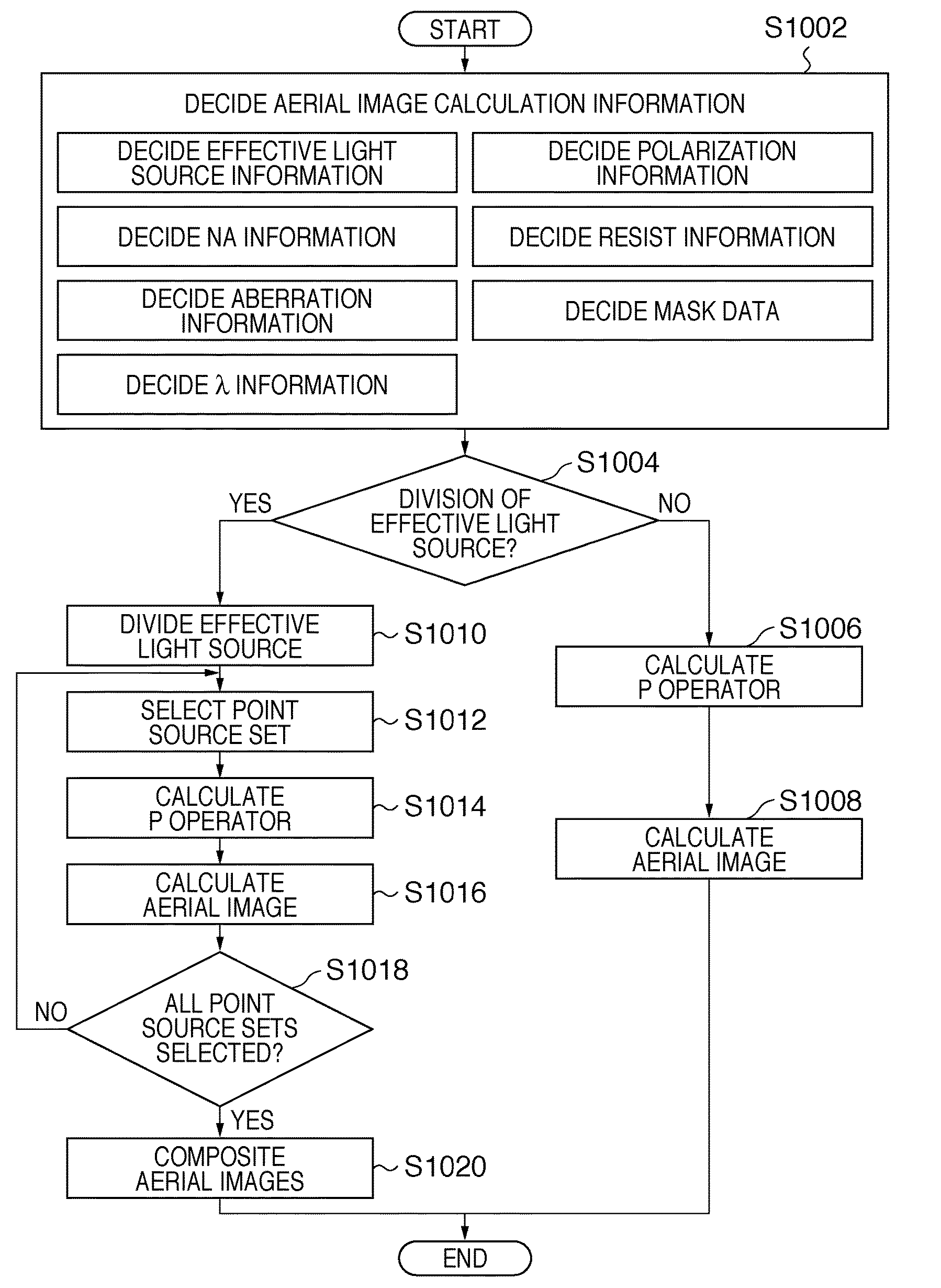
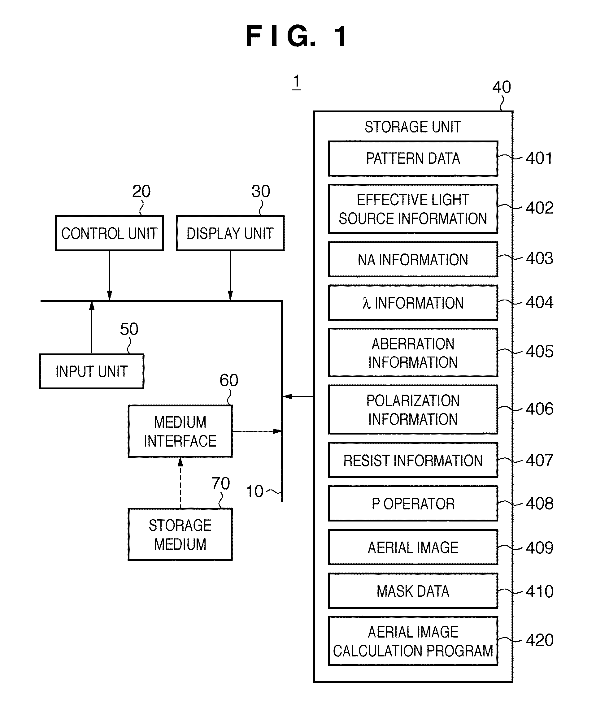
[0150]In a first embodiment, Xeon® 32 bit was used as a CPU included in a control unit 20 of a processing apparatus 1, and a memory of about 2 Gbytes was used as a storage unit 40. An aerial image calculation program 420 was created using MATLAB®. The time in calculating an aerial image 409 while dividing the effective light source was compared with the time in calculating the aerial image 409 without dividing the effective light source.

[0151]In the first embodiment, assume that the NA of the projection optical system of the exposure apparatus is 0.73 (corresponding to NA information 403), and the wavelength of exposure light is 248 nm (corresponding to λ information 404). The projection optical system has no aberration (corresponding to aberration information 405), the illumination light has no polarization (corresponding to polarization information 406), and a resist to be applied to a wafer is not taken into consideration (corresponding to resist information 407). Quadrupole illu...

second embodiment

[0156]In a second embodiment, Xeon® 32 bit was used as a CPU included in a control unit 20 of a processing apparatus 1, and a memory of about 2 Gbytes was used as a storage unit 40. An aerial image calculation program 420 was created using MATLAB®. The time in calculating an aerial image 409 while dividing the effective light source was compared with the time in calculating the aerial image 409 without dividing the effective light source.

[0157]In the second embodiment, assume that the NA of the projection optical system of the exposure apparatus is 0.73 (corresponding to NA information 403), and the wavelength of exposure light is 248 nm (corresponding to λ information 404). The projection optical system has no aberration (corresponding to aberration information 405), the illumination light has no polarization (corresponding to polarization information 406), and a resist to be applied to a wafer is not taken into consideration (corresponding to resist information 407). Circular illu...

fourth embodiment

[0167]In a fourth embodiment, an exposure apparatus 100 which executes exposure processing by adjusting exposure conditions based on an aerial image (a light intensity distribution formed on the image plane of the projection optical system) calculated by the above-described processing apparatus 1 will be described. FIG. 14 is a schematic block diagram showing the arrangement of the exposure apparatus 100.

[0168]The exposure apparatus 100 is an immersion exposure apparatus which transfers the pattern of a mask 130 onto a wafer 150 by step-and-scan via a liquid LW supplied between a projection optical system 140 and the wafer 150. The exposure apparatus 100 can also use a step-and-repeat method or any other exposure method.

[0169]As shown in FIG. 14, the exposure apparatus 100 includes an illumination optical system 120, a mask stage 135 on which the mask 130 is placed, the projection optical system 140, a wafer stage 155 on which the wafer 150 is placed, a liquid supply / recovery unit 1...


PUM

PropertyMeasurementUnit
light intensity distributionaaaaaaaaaa
plurality of areasaaaaaaaaaa
light intensity distributionsaaaaaaaaaa

Abstract

A computer readable medium containing computer-executable instructions which cause a computer to execute processing steps that calculate a light intensity distribution formed on an image plane of a projection optical system. When executed, the medium causes a computer to execute the steps of dividing an effective light source into the plurality of areas, generating, for each of the plurality of areas, a plurality of shifted pupil functions by shifting a pupil function in accordance with a position of each of divided point sources, defining, for each of the plurality of areas, a matrix including the plurality of pupil functions, calculating, for each of the plurality of areas, eigenvalues and eigenfunctions by performing singular value decomposition of the matrix, and calculating, for each of the plurality of areas, the light intensity distribution based on a diffracted light distribution from the mask and the eigenvalues and the eigenfunctions.

Description

BACKGROUND OF THE INVENTION[0001]1. Field of the Invention[0002]The present invention relates to a computer readable medium and an exposure method.[0003]2. Description of the Related Art[0004]To manufacture semiconductor devices by photolithography, projection exposure apparatuses are used which project a circuit pattern drawn on a mask (or reticle) onto a substrate such as a wafer via a projection optical system, thereby transferring the circuit pattern. Recent advanced microfabrication technologies for semiconductor devices require improved resolutions (higher resolutions) of the projection exposure apparatuses.[0005]Increasing the NA (Numerical Aperture) of the projection optical system and shortening the wavelength of exposure light are conventionally known means for achieving a higher resolution of a projection exposure apparatus. RET (Resolution Enhanced Technology) is also attracting attention, which improves the resolution of a projection exposure apparatus by reducing a k1 ...

Claims


Application Information

Patent Timeline
Patent Type & Authority Applications(United States)
IPC IPC(8): G03B27/42G03F7/20H01L21/027
CPCG03F7/70666G03F7/705G06F9/44G06F9/455G06F15/0208
Inventor SEKINE, YOSHIYUKIYAMAZOE, KENJI
Owner CANON KK
Why Eureka
Try Eureka