Optical element for gas laser and gas laser apparatus using the same

a technology of optical elements and lasers, applied in the direction of laser details, instruments, active medium materials, etc., can solve the problems of crystal not being used as a laser chamber window, unable to achieve high-precision polishing with low surface coarseness, and unable to achieve the effect of preventing surface damage, low surface coarseness, and high precision polishing

Active Publication Date: 2010-03-04
GIGAPHOTON
View PDF7 Cites 8 Cited by
  • Summary
  • Abstract
  • Description
  • Claims
  • Application Information

AI Technical Summary

Benefits of technology

[0023]Thus, an optical element for a gas laser according to the present invention makes it possible to realize high precision polishing with low surface coarseness by using the (111) crystal face as crystal surface and prevent the surface damage that can be caused by laser beam irradiation due to latent flaws. Then, it is possible to raise the degree of polarization by arranging the crystal so as to reduce the Fres

Problems solved by technology

However, the above-described conventional art has the following problem.
Patent Document 1 does not describe any specific means for actually making an optical axis pass perpendicularly relative to the (111) crystal face of a window that operates as optical element and also making the surface thereof show the Brewster angle and then a crystal orientation face of calcium fluoride crystal that is hard to a certain extent cannot be selected as the face to be cut to produce a window if the above two objectives are to be achieved simultaneously so that it is not possible to realize high precision polishing with low surface

Method used


Image

  • Optical element for gas laser and gas laser apparatus using the same
  • Optical element for gas laser and gas laser apparatus using the same
  • Optical element for gas laser and gas laser apparatus using the same

Examples


Embodiment Construction

[0043]Now, an optical element for an ultraviolet gas laser and an ultraviolet gas laser according to the present invention will be described by way of embodiments.

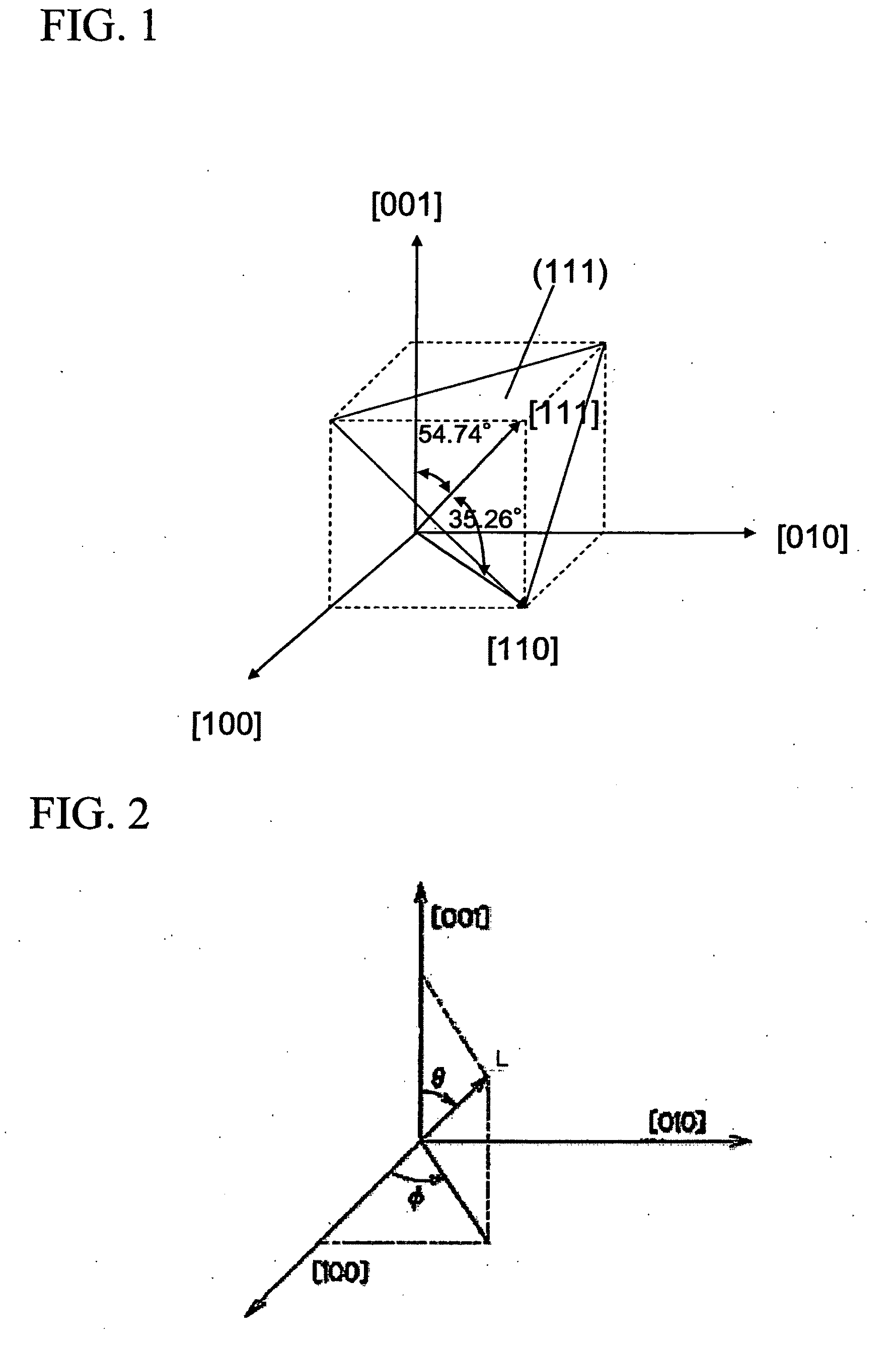
[0044]FIG. 1 is a schematic illustration of the crystal lattice of CaF2. In the embodiment that will be described below, CaF2 crystal is cut along the (111) crystal face in accordance with the crystal orientation. CaF2 crystal has a structure of face-centered cubic lattice as illustrated in FIG. 1.

[0045]As angles θ and ø are defined for the proceeding direction L of light relative to the axes [001] and [100] of CaF2 crystal respectively as illustrated in FIG. 2, the direction of the [111] axis is defined by ø=45° and θ=54.74° as illustrated in FIG. 2. The surface of the (111) crystal face is hardest and hence harder than any other surfaces of crystal axes and hence it can be polished with low surface coarseness and few latent flaws.

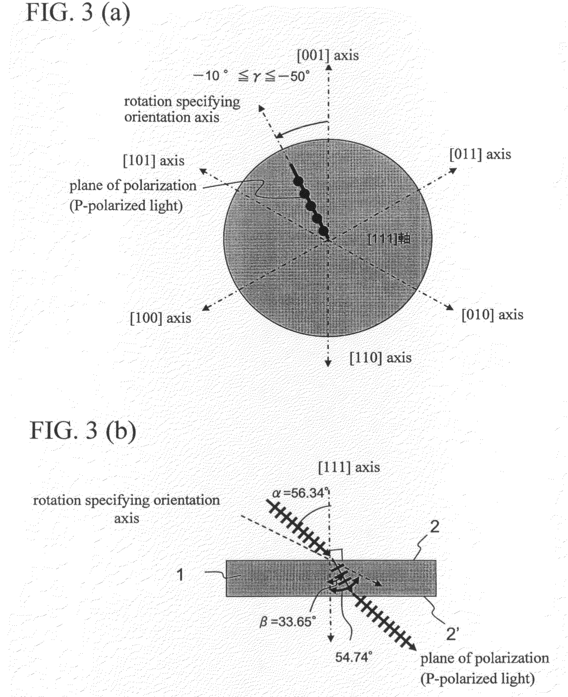
[0046]FIG. 3 is schematic views of window 1 formed by using CaF2 (calcium fluoride) accordin...


PUM


Abstract

At least either of the light entering plane or the light exiting plane is parallel to the (111) crystal face of the CaF2 crystal and the laser beam entering from the entering plane passes through the plane located between the [111] axis and the first azimuth axis in the locus of rotation of the [001] axis around the [111] axis and including the [111] axis and the first azimuth axis, the plane located between the [111] axis and the second azimuth axis in the locus of rotation of the [010] axis around the [111] axis and including the [111] axis and the second azimuth axis or the plane located between the [111] axis and the third azimuth axis in the locus of rotation of the [100] axis around the [111] axis and including the [111] axis and the third azimuth axis and exits from the exiting plane.

Description

CROSS REFERENCE TO RELATED APPLICATIONS[0001]This application claims benefit of Japanese Application No. 2008-277714 filed in Japan on Oct. 29, 2008, the contents of which are incorporated by this reference.BACKGROUND OF THE INVENTION[0002]The present invention relates to an optical element for a gas laser and also to a gas laser apparatus using the same. More particularly, the present invention relates to an optical element for an ultraviolet gas laser to be used in a semiconductor exposure apparatus having an excimer laser or a molecular fluorine laser and also to a gas laser apparatus using the same.(Exposure Light Source)[0003]In the trend of making semiconductor integrated circuits finer and more integrated, an improved resolution is required for semiconductor exposure apparatus. To meet this demand, efforts are being paid to use shorter wavelength for the light emitted from an exposure light source. A gas laser apparatus is being popularly employed as exposure light sources in...

Claims


Application Information

Patent Timeline
IPC IPC(8): H01S3/08
CPCG02B1/02H01S3/005H01S3/0057H01S3/2251H01S3/08054H01S3/10061H01S3/08009
Inventor WAKABAYASHI, OSAMUNAGAI, SHINJIKAKIZAKI, KOUJITANAKA, SATOSHI
Owner GIGAPHOTON
Why Eureka
Try Eureka