Drill

a drill and point technology, applied in the field of drills, can solve the problems of reducing the reducing affecting the service life of the tool, so as to prevent wear and fracture of the outer peripheral corner of the cutting edge, prevent chip welding and accumulation on the point portion of the drill, and prevent the effect of chip welding

Inactive Publication Date: 2010-03-04
OSG +1
View PDF9 Cites 38 Cited by
  • Summary
  • Abstract
  • Description
  • Claims
  • Application Information

AI Technical Summary

Benefits of technology

[0013]A drill of the invention has a cutting edge formed in a convex arc shape having a curvature radius that is greater than or equal to 0.25 times and less than or equal to 1 times the drill diameter. In addition, a radial rake angle at the outer peripheral portion of the cutting edge is greater than or equal to −15 degrees and less than or equal to −60 degrees, and a corner portion, which is closer to the center of a point portion of the drill, of a thinned portion is formed in an arc shape having a curvature radius of at least 0.1 mm and not greater than 0.05 times the drill diameter. Consequently, even in a case where high feed machining, in which a feed per revolution of the drill is higher than normal, is performed, wear and fracture of the outer peripheral corner of the cutting edge can be prevented. Moreover, chip removal can be facilitated and thus chip welding and accumulation on the point portion of the drill can also be prevented, so damage of the cutting edge can be prevented, thereby the life of the drill can be lengthened.
[0014]Furthermore, in a case where the present invention is applied to a three-edged drill that has three flutes and three cutting edges, in addition to the aforementioned effects, drill runout during drilling can be prevented, thus drilling precision can be improved.
[0015]Moreover, in a case where the present invention is applied to a drill provided with a chisel edge, a point portion of the drill is not moved when drilling stars, compared with a case of a drill that has no chisel edge, so the drilling precision can be improved. Furthermore, chip welding and accumulation on the chisel edge can be prevented.
[0016]In addition, in a case where the drill of the present invention is formed of ultrahard material, wear of the drill can be prevented more effectively and thus the life of the drill can be further lengthened.
[0017]Moreover, when a linear-shape center cutting edge is formed at a portion between the cutting edge of the drill of the present invention and the corner portion of the thinned portion that is on a drill rotational direction side with respect to the cutting edge, a space for a chip room for collecting chips can be secured, thereby smooth chip removal can be allowed. Consequently, chip welding and accumulation on the chisel edge can also be prevented.
[0018]In addition, in a case where a center cutting edge in an arc shape having a larger curvature radius than the curvature radius of the cutting edge is formed at a portion between the cutting edge of the drill of the present invention and the corner portion of the thinned portion that is on the drill rotational direction side with respect to the cutting edge, a space for a chip room for collecting chips can be secured, thereby smooth chip removal can be allowed. Consequently, chip welding and accumulation on the chisel edge can also be prevented.

Problems solved by technology

Furthermore, even in a case where the drill is used under normal conditions in which the feed per revolution is 2 to 3% of the drill diameter, the corner portion of the drill cutting edge may often be fractured or completely worn out to reach durability limit.
As a consequence, edge fracture is unlikely to occur, thus the tool life can be lengthened.

Method used


Image

  • Drill
  • Drill
  • Drill

Examples


first embodiment

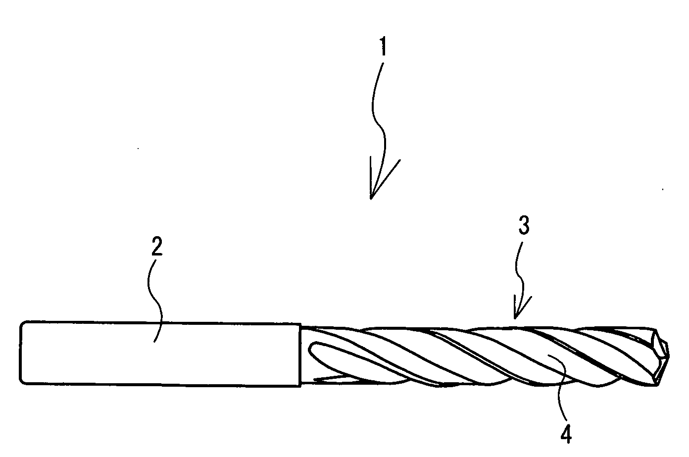
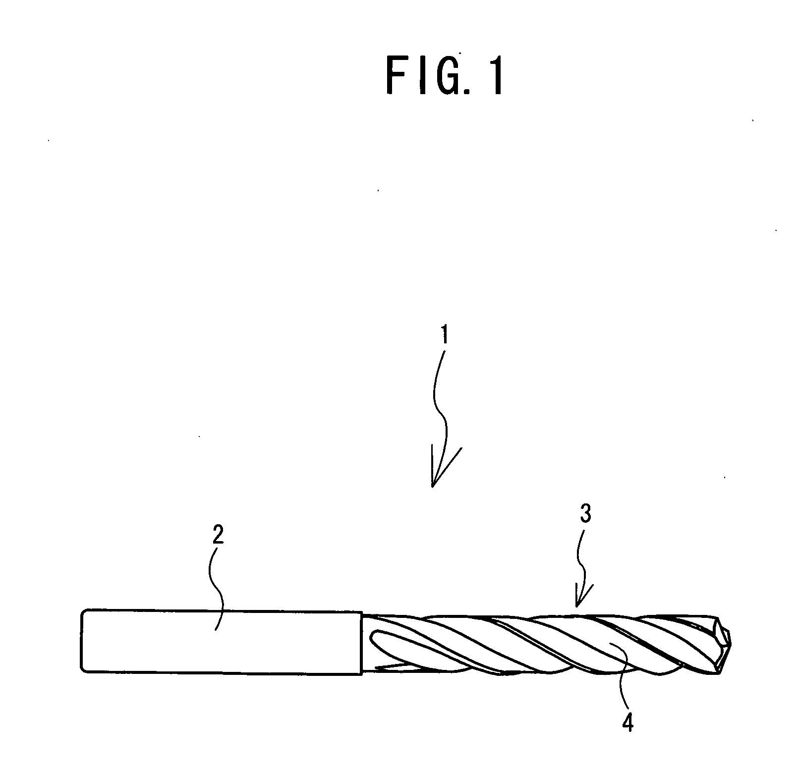
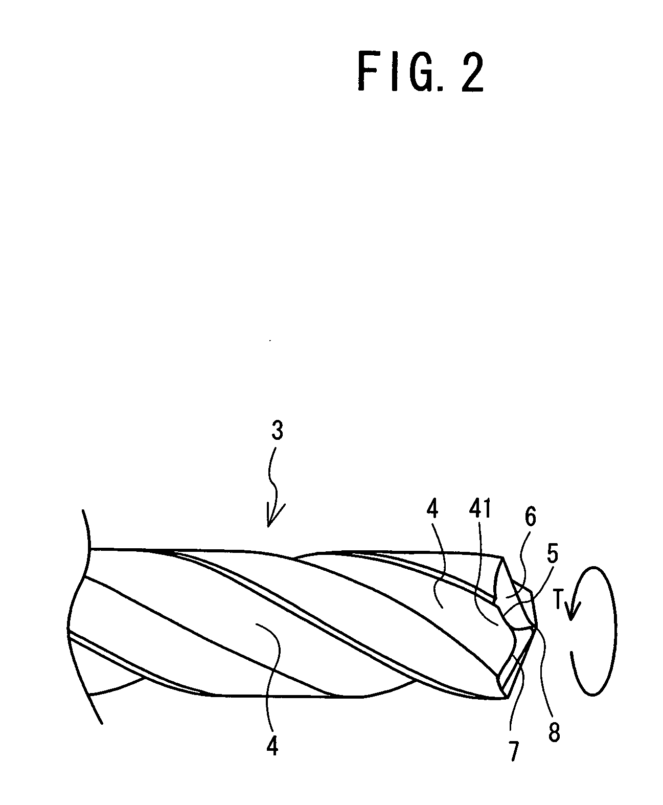
[0020]Hereafter, a drill 1 according to the present invention will be described with reference to FIGS. 1 to 3. FIG. 1 is a side view of the drill 1, FIG. 2 is an enlarged view of a point portion of a body 3 of the drill 1, and FIG. 3 is a front view of a point portion of the drill 1. As shown in FIG. 1, the drill 1 according to the present embodiment is formed in a substantially cylindrical shape, is made of hard material such as ultrahard material and high-speed tool steel, and includes a shank 2 and a body 3 which extends from the shank 2. Furthermore, the body 3 is provided with three helical flutes 4 for removing chips and the point portion of the body 3 is provided with three cutting edges 5. Accordingly, the drill 1 is a three-edged drill as well as a twist drill for high feed machining, which is used for high feed machining in which the feed per revolution is higher than normal.

[0021]Next, the structure of the point portion of the drill 1 will be described with reference to ...

second embodiment

[0048]FIG. 4 is a front view of a point portion of a drill 11 according to a

third embodiment

[0049]FIG. 5 is a front view of a point portion of a drill 12 according to a

[0050]FIG. 6 is a front view of a point portion of a drill 13 of a first test example.

[0051]FIG. 7 is a front view of a point portion of a drill 14 of a second test example.

[0052]FIG. 8 is a front view of a point portion of a drill 15 of a third test example.

[0053]FIG. 9 is a front view of a point portion of a drill 16 of a fourth test example.

[0054]FIG. 10 is a front view of a point portion of a drill 17 of a first comparison example.

[0055]FIG. 11 is a table showing the test results of a first durability test.

[0056]FIG. 12 is a graph showing the test results of the first durability test.

[0057]FIG. 13 is a front view of a point portion of a drill 18 of a fifth test example.

[0058]FIG. 14 is a front view of a point portion of a drill 19 of a sixth test example.

[0059]FIG. 15 is a front view of a point portion of a drill 20 of a seventh test example.

[0060]FIG. 16 is a front view of a point portion of a drill 21 ...


PUM

PropertyMeasurementUnit
radial rake angleaaaaaaaaaa
curvature radiusaaaaaaaaaa
radial rake angleaaaaaaaaaa

Abstract

A drill in which a flute is formed from a point to a base end side of a body of the drill, on a side face to be rotated about an axis, a cutting edge is formed between a wall surface of the flute which faces a drill rotational direction side and a flank at the point of the body, and a thinned portion is provided to a web portion of the point. The cutting edge is formed in a convex arc shape with a curvature radius 0.25 to 1 times a drill diameter; a radial rake angle at an outer peripheral portion of the cutting edge is −60 to −15 degrees; a corner portion, closer to the center of the point, of the thinned portion is formed in an arc shape with a curvature radius of at least 0.1 mm and not greater than 0.05 times the drill diameter; and the drill includes three flutes and three cutting edges.

Description

TECHNICAL FIELD[0001]The present invention relates to a drill, and more specifically, to a high feed drill of which a feed per revolution is higher than normal.BACKGROUND ART[0002]Conventionally, in a case where high feed machining, in which a feed per revolution exceeds 5% of a drill diameter, is performed with a drill with a linear cutting edge, fracture or the like of the cutting edge is likely to occur due to insufficient strength of a corner portion of the cutting edge, so the machining may be prevented in some cases. Furthermore, even in a case where the drill is used under normal conditions in which the feed per revolution is 2 to 3% of the drill diameter, the corner portion of the drill cutting edge may often be fractured or completely worn out to reach durability limit.[0003]Therefore, Patent Document 1 proposes a drill which has a cutting edge with fracture resistance and which enables favorable chip curling as well as deep hole drilling and through hole drilling in a stab...

Claims


Application Information

Patent Timeline
Patent Type & Authority Applications(United States)
IPC IPC(8): B23B51/02
CPCB23B51/02B23B2222/32B23B2228/24B23B2251/04Y10T408/909B23B2251/18B23B2251/202Y10T408/9097B23B2251/14
Inventor MASUDA, NORIHIROAOKI, WATARU
Owner OSG
Why Eureka
Try Eureka