Ceramic honeycomb filter and its production method

a honeycomb filter and ceramic technology, applied in the field of ceramic honeycomb filter, can solve the problems of increased pressure loss, adverse effects on human beings and the environment, melting erosion of the honeycomb filter, etc., and achieve the effect of reducing melting erosion and effective absorption of pm hea

Active Publication Date: 2010-03-11
HITACHI METALS LTD
View PDF3 Cites 27 Cited by
  • Summary
  • Abstract
  • Description
  • Claims
  • Application Information

AI Technical Summary

Benefits of technology

[0007]Accordingly, an object of the present invention is to provide a honeycomb filter capable of more effectively absorbing the combustion heat of PM by outlet-side plugs than conventional honeycomb filters, thereby reducing melting erosion, and its production method.DISCLOSURE OF THE INVENTION
[0008]As a result of intensive research in view of the above object, the inventors have found that by providing the outlet-side plugs with small porosity, and by providing the upstream-side end surfaces of the outlet-side plugs with large roughness, the combustion heat of PM can be effectively absorbed, thereby remarkably reducing melting erosion. The present invention has been completed based on such finding.

Problems solved by technology

When such exhaust gas is released into the atmosphere, it may adversely affect human beings and the environment.
As PM continues to be captured by the cell walls 2, penetrating holes are clogged with PM on and in cell the walls, resulting in increased pressure loss when the exhaust gas passes through the honeycomb filter.
However, when burning a large amount of PM captured, combustion heat causes melting erosion in the honeycomb filter.
However, partial increase in the cell wall thickness or partial decrease in the cell wall porosity necessitates new steps, suffering large cost increase despite insufficient prevention of the melting erosion of the honeycomb filter.
Although longer outlet-side plugs surely provide the entire honeycomb filter has higher heat capacity, the combustion heat of PM is not effectively absorbed by the entire outlet-side plugs, failing to sufficiently prevent melting erosion.
However, it is difficult to apply the technologies of JP 2000-279729 A, JP 10-52618 A and WO2004 / 113252 A for controlling the porosity and surface roughness of cell walls to plugs.

Method used


Image

  • Ceramic honeycomb filter and its production method
  • Ceramic honeycomb filter and its production method
  • Ceramic honeycomb filter and its production method

Examples


example 1

Production of Honeycomb Filter

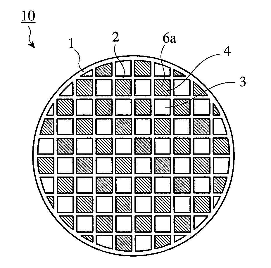
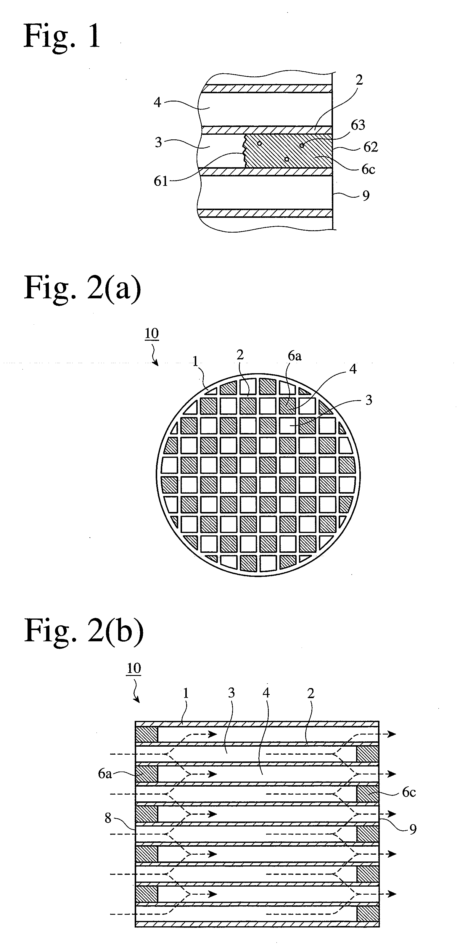
[0033]To produce the honeycomb filter 10 shown in FIG. 2 by a known method, kaolin powder, talc powder, silica powder, alumina powder and aluminum hydroxide powder were mixed to prepare cordierite-forming material powder comprising 50% by mass of SiO2, 35% by mass of Al2O3 and 15% by mass of MgO. The amounts of these components may be adjusted in a range of 48-52% by mass for SiO2, 33-37% by mass for Al2O3 and 12-15% by mass for MgO. This powder was mixed with methylcellulose and hydroxypropyl methylcellulose as binders, a lubricant, and a foamed resin as pore formers. After thorough dry-blending, water was added to carry out sufficient kneading to prepare a moldable ceramic material. This moldable material was extrusion-molded and cut to produce a honeycomb-structure, molded article. This molded article was dried and sintered to produce a cordierite honeycomb structure. This ceramic honeycomb structure had an outer diameter of 150 mm, a length of 202 m...

examples 11-13

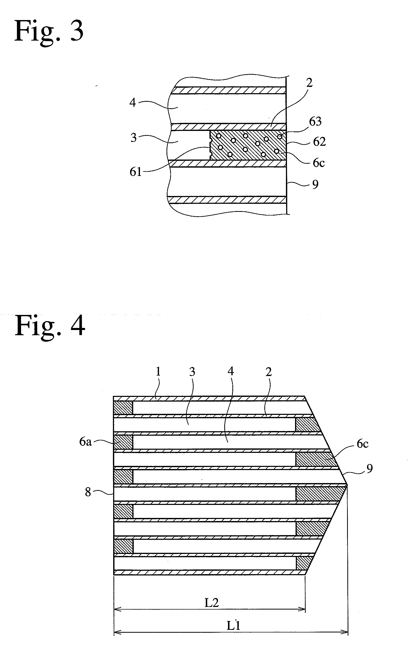
[0040]The honeycomb filters 10 of Examples 11 and 12 were produced in the same manner as in Examples 9 and 10, except that a plugging material slurry was supplied to the flow paths of each honeycomb structure, into which water was introduced in advance, and dried with the exhaust-gas-outlet-side end 9 upward, and that large-particle-size cordierite powder was sprayed onto each honeycomb structure placed with its exhaust-gas-inlet-side end 8 upward. The impregnation of the honeycomb structure with water was conducted by immersing portions corresponding to the outlet-side plugs 6c in water. The honeycomb filter 10 of Example 13 was produced in the same manner as in Example 12, except for changing the particle size of cordierite powder accumulated on the upstream-side end surfaces 61 of the outlet-side plugs 6c.

[0041]With respect to the honeycomb filters of Examples 11-13, the measurement of the length and porosity of the outlet-side plugs 6c and the surface roughness Ra of the upstre...

example 14

[0043]The same honeycomb filter as in Example 7 was produced to evaluate PM-burning efficiency by the following procedure.

Evaluation of PM-burning Efficiency

[0044]With air supplied at a flow rate of 5 Nm3 / min, pressure difference (pressure loss B) between the upstream side and the downstream side in the honeycomb filter was measured. 8 g / h of carbon powder having a particle size of 0.042 μm, which was generated by a fine particle generator, was introduced together with air at a flow rate of 15 Nm3 / min into the honeycomb filter through the exhaust-gas-inlet-side end 8 for 1 hour, so that the carbon powder was accumulated in the outlet-side-sealed flow paths 3 of the honeycomb filter. Further, air at 680° C. was supplied at 5 Nm3 / min to the honeycomb filter through the exhaust-gas-inlet-side end 8. While burning carbon powder, pressure difference (pressure loss A) between the upstream side and the downstream side in the honeycomb filter was measured, and the time period T until the ra...


PUM

PropertyMeasurementUnit
surface roughness Raaaaaaaaaaa
porosityaaaaaaaaaa
porosityaaaaaaaaaa

Abstract

A ceramic honeycomb filter comprising a honeycomb structure having large numbers of flow paths partitioned by porous cell walls, and plugs alternately formed in the flow paths on the exhaust-gas-inlet and outlet sides, the outlet-side plugs having porosity of 65% or less, and the upstream-side end surfaces of the outlet-side plugs having surface roughness Ra of 13-50 μm.

Description

FIELD OF THE INVENTION[0001]The present invention relates to a ceramic honeycomb filter used for capturing particulate matter in an exhaust gas discharged from diesel engines, etc. to clean the exhaust gas, and its production method.BACKGROUND OF THE INVENTION[0002]An exhaust gas emitted from diesel engines contains PM (particulate matter) based on carbonaceous soot and SOF (soluble organic fraction) of high-boiling-point hydrocarbons. When such exhaust gas is released into the atmosphere, it may adversely affect human beings and the environment. For this reason, a PM-capturing ceramic honeycomb filter, which may be called “honeycomb filter” in short, has been disposed in an exhaust pipe connected to a diesel engine. One example of honeycomb filters for purifying an exhaust gas by removing particulate matter is shown in FIGS. 2(a) and 2(b). The honeycomb filter 10 comprises a ceramic honeycomb structure comprising porous cell walls 2 defining large numbers of outlet-side-sealed flow...

Claims


Application Information

Patent Timeline
Patent Type & Authority Applications(United States)
IPC IPC(8): B01D35/04B01D39/20B05D3/02
CPCB01D46/2425B01D46/244C04B2235/349C04B2235/3445C04B2235/3427B01D46/2459B01D46/2466B01D2046/2433B01D2046/2492B01D2046/2496B01D2279/30C04B35/195C04B38/0009C04B2111/00793C04B2235/3217C04B38/0054C04B38/0074B01D46/2498B01D46/24491B01D46/2482B01D39/20B01D46/00F01N3/022B01J35/04
Inventor KONOMI, MASAKAZUSUWABE, HIROHISA
Owner HITACHI METALS LTD
Why Eureka
Try Eureka