Weld repair process and article repaired thereby

Inactive Publication Date: 2010-03-11
GENERAL ELECTRIC CO
View PDF5 Cites 16 Cited by
  • Summary
  • Abstract
  • Description
  • Claims
  • Application Information

AI Technical Summary

Benefits of technology

[0008]According to yet another aspect of the present invention, an article is provided that is repaired by a method comprising the steps of depositing at least a first weld repair layer on a surface of the article so as to form a heat-affected zone in the article beneath the surface, the first weld repair layer being formed of a nickel chromium iron alloy. Locally heat treating the first weld repair layer and the heat-affected zone at a temperature above the critical A1 temperature of the article, the heat treating step reducing the hardness of the first weld repair layer and at least a portion of the heat-affected zone. Depositing at least one additional weld repair layer on the first weld repair layer

Problems solved by technology

Although steam turbine components made from CrMo and CrMoV steels exhibit a long service life, it is possible that wear, erosion, corrosion, shock, fatigue and/or overstress will occur, necessitating repair or replacement of the component.
Because weld-induced hardness is detrimental to creep and fatigue properties, FIG. 2 evidences that post-weld heat treatment is needed to promote these desirable properties in a weld-repaired component.
A drawback to this process is the cost of the heat treatment operation, the time involved to perform the operation, and the possibility of distorting the component.
These drawbacks are particularly problematic in the repair of high-temperature components that have heightened creep resistance requirements, such as the CrMoV turbine lower shell of

Method used


Image

  • Weld repair process and article repaired thereby
  • Weld repair process and article repaired thereby
  • Weld repair process and article repaired thereby

Examples


Embodiment Construction

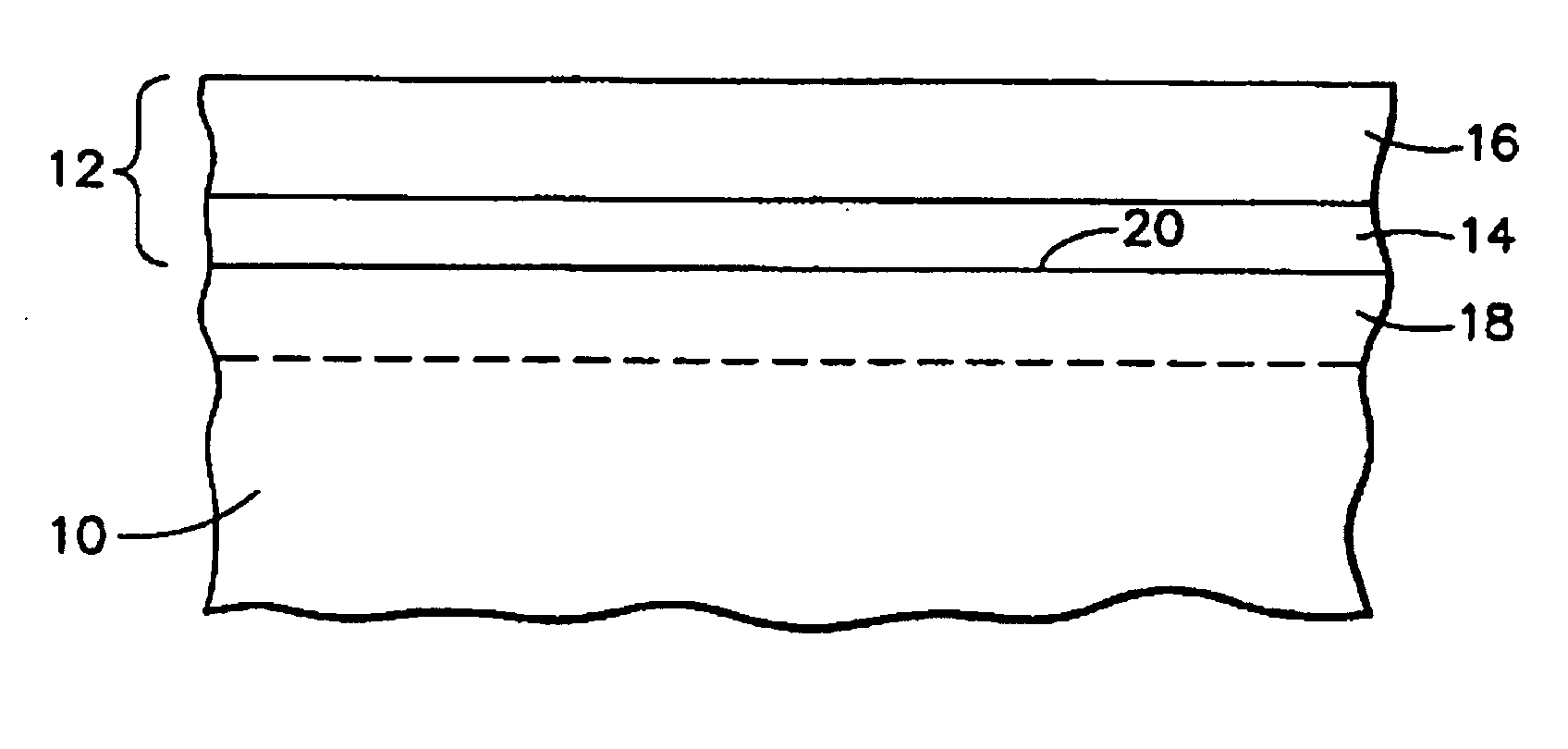
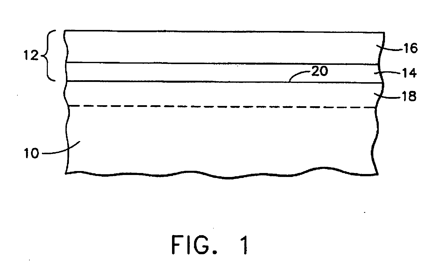
[0012]FIG. 1 represents in cross-section a low-alloy steel article that has been repaired in accordance with this invention. An example of such an article is a component of a steam turbine, though a wide variety of components could be repaired by the method of this invention. As represented in FIG. 1, the article generally includes a base material 10 on which a weld repair 12 has been built up to restore the article to its original dimensions after a damaged portion has been removed. The weld repair 12 generally includes one or more weld repair layers that have been deposited on the surface of the base material 10 to yield a surfacing weld repair 14. In turn, a fill weld layer 16 is shown as having been deposited on the surfacing weld repair 14. The interface between the surfacing weld repair 14 and the base material 10 is termed the fusion line 20 of the weld repair 12. According to this invention, when repairing CrMoV and CrMo alloys of the type used to form steam turbine componen...


PUM

PropertyMeasurementUnit
Temperatureaaaaaaaaaa
Lengthaaaaaaaaaa

Abstract

A method for repairing a steel alloy article, and an article repaired thereby, is provided and comprises the steps of depositing at least a first weld repair layer on a surface of the article so as to form a heat affected zone in the article beneath the surface. Locally heat treating the first weld repair layer and at least a portion of the heat affected zone adjacent the first weld repair layer at a temperature above the critical A1 temperature of the steel alloy article. Depositing at least one additional weld repair layer on the first weld repair layer without forming additional heat affected zone in the surface of the article. The first weld repair layer and the at least one additional weld repair layer are comprised of a material chosen from the group consisting of nickel chromium—iron alloys, cobalt base alloys, ERNiCr-3, ENiCrFe-3, ERNiCrMo-3, ERNiFeCr-2, ERCoCr-A, ERCoCr-E, CrMo alloys and CrMoV alloys. The article can be placed in service without a post-weld heat treatment of the additional weld repair layer following the step of depositing the additional weld repair layer.

Description

BACKGROUND OF THE INVENTION[0001]The present invention relates to welding processes. More particularly, this invention relates to a method for weld repairing a steel alloy article, the method entailing a localized heat treatment technique that is applied to a limited intermediate region of the weld repair prior to completion of the weld repair, and avoids a full post-weld heat treatment of the article.[0002]Chromium-molybdenum (CrMo) and chromium-molybdenum vanadinun (CrMoV) low-alloy steels have found wide use for components of steam turbines and other power plant applications. These alloys have been selected in part on the basis of creep and fatigue properties due to the severe operating conditions of steam turbine components. Although steam turbine components made from CrMo and CrMoV steels exhibit a long service life, it is possible that wear, erosion, corrosion, shock, fatigue and / or overstress will occur, necessitating repair or replacement of the component. In the past, repai...

Claims


Application Information

Patent Timeline
IPC IPC(8): B23K31/02
CPCC22C19/00F01D5/005F05C2201/0463F05C2201/0466B23K9/044B23K2201/001F05D2300/131C21D9/50F05D2220/31F05D2230/232F05D2300/11F05D2300/132B23K2203/08B23K2101/001B23K2103/04B23K2103/18B23K2103/26
Inventor SASSATELLI, JOHN M.NOLAN, JOHN F.PORTEOUS, NICHOLAS D.PASSINO, JR., MARK J.CRAWMER, GERALD R.COOK, CARTER S.
Owner GENERAL ELECTRIC CO
Why Eureka
Try Eureka