
System for Electrical Apparatus Testing

a technology for electrical equipment and circuits, applied in the direction of measuring devices, testing dielectric strength, instruments, etc., can solve the problems of corroded contacts and weak connections, uninterrupted operation is often critical, and corroded contacts can even be sources of danger, so as to achieve little additional equipment or capabilities

Inactive Publication Date: 2010-03-11
SKF USA INC
View PDF27 Cites 30 Cited by
  • Summary
  • Abstract
  • Description
  • Claims
  • Application Information

AI Technical Summary

Benefits of technology

[0013]The present invention provides a way to monitor for and quantitatively identify incipient high-R contacts in a way that is more convenient than most existing techniques. It provides a fundamentally new technique that overcomes many of the problems of existing methods. It presents a fully automated technique that can monitor for high-R connections located both upstream and downstream during normal load operation. It can also provide this ability based on the existing voltage and current measurements so little additional equipment or capabilities are required.
[0014]In a variety of embodiments the present invention presents a new understanding from which even upstream faults can not only be detected, but can be quantified and located with a high degree of accuracy. Embodiments of the invention can provide techniques that quantify even incipient faults by using unique conditions that usually already exist in normal operation of the machine or motor circuitry. These techniques can be fully automated to operate substantially continuously for multiphase and even single phase machine or motor topologies. They can even be augmented to detect downstream faults in a manner that avoids many of the dangers and difficulties of existing techniques.
[0015]Accordingly, it is an objective of embodiments of the present invention to provide techniques that overcome the limitations of the most existing test methods. An objective is to provide a system that can be implemented with what is often an existing measurement access so that new risks or expenses are either not created or are minimized. It is also an objective to provide test capabilities that can determine potential faults with a high degree of accuracy without intrusive test activities.

Problems solved by technology

Continued, uninterrupted operation is often critical to the devices for which they are a component.
Unfortunately, their operation can at times be attended by corroded contacts and weakened connections.
As shown thermographically in FIG. 3, corroded contacts can even be a source of danger.
These problems, which are common in industry, are usually initiated due to a combination of poor workmanship (mainly under-tightening of connectors), loose connections, or corrosion / oxidation / contamination / damage in the contact surface.
Once a high-R contact is created, repeated thermal cycling and vibration may deteriorate the contact quality at an elevated rate and may increase the contact resistance.
This, combined with vibration, can loosen the connection which may increase the contact resistance and local temperature.
If the contact resistance increases to an unsafe level, this can result in localized overheating as shown in FIG. 3, supply voltage unbalance, and / or sparking.
Local thermal overloading at the contact may be one of the leading root causes of failure in electrical distribution systems.
This can cause open circuit failures (melting of conductor / contact) or short circuit failures (insulation damage) in the electric circuit.
Supply voltage unbalance can cause negative sequence current flow in the load, which can result in thermal overheating and vibration of machine or motor loads.
This can accelerate the degradation of machine or motor insulation, which is often one of the main root causes of failure.
High-R connections can also reduce the system efficiency and can increase the safety risks in addition to decreasing the distribution circuit and machine or motor reliability, as explained above.
The efficiency of the electrical distribution system and load can suffer when high-R contacts are present.
According to one study, 36% of the electrical distribution system problems that result in decreased efficiency are due to poor connections.
As mentioned, the efficiency of machine or motor loads can be decreased when the input supply voltage is unbalanced, since negative sequence current can cause additional winding losses and can induce negative torque that decreases the output.
It is known that overheating and sparking at the high-R contact can initiate electric fires, and that a significant portion of building fires are caused by poor contacts.
Unfortunately, upstream connection problems are particularly difficult to assess because the upstream circuitry can usually only be viewed in its entirety, that is, from its very source to the point of measurement.
Unlike the downstream path which can be limited by the measurement point to only the machine or motor and perhaps an associated control center or Motor Control Center (MCC), the upstream circuitry is almost a complete unknown and is almost completely unpredictable.
This technology's disadvantages are that the testing needs to be performed offline and it needs to be connected directly to the voltage buss.
The most expensive machine or motors in industry, however, tend to be medium or high voltage.
A further disadvantage to this method is that it is usually only capable of finding high resistance connections downstream from where the equipment is connected.
Although it is very effective for detecting high-R problems, its limitations of being performed off-line and usually only being able to identify problems downstream from where the test is performed remain as significant drawbacks.
This usually requires that the Motor Control Center (MCC) be opened and this can cause safety hazards.
As an online test, the intrusion of a voltage measurement can create risks.
This also usually means that the Motor Control Center (MCC) either needs to be opened—causing obvious safety arc flash hazards—or suitable IR windows need to be installed in all locations with a potential of failure.
IR thermography can be safer, faster, and more accurate compared to the voltage drop test for finding high-R contacts, but it is attended by the drawbacks of requiring good line of sight to the problem and expensive equipment or service.
These on-line tests can only be performed when the machine is in use, and the results depend on the load current making it difficult to assess the severity of the fault.
All the tests available for monitoring high-R connections are inconvenient since they are either offline or walk-around type tests and do not provide continuous monitoring capability.
The validity of the method has been shown experimentally; however, the method requires intensive computation and training of the neural network.
Like the neural network technique, this newer technique appears limited by its symmetrical component based nature.
Thus, it appears that it can only detect high-R problems located downstream from the point of voltage measurement.
Unfortunately none of the above techniques fulfill these criteria.

Method used


Image

  • System for Electrical Apparatus Testing
  • System for Electrical Apparatus Testing
  • System for Electrical Apparatus Testing

Examples


Embodiment Construction

[0049]The present invention includes a variety of aspects, which may be combined in different ways. The following descriptions are provided to list actions and elements and to describe some of the embodiments of the present invention. These elements are listed with initial embodiments, however it should be understood that they may be combined in any manner and in any number to create additional embodiments. The variously described examples and preferred embodiments should not be construed to limit the present invention to only the explicitly described systems, techniques, and applications. Further, this description should be understood to support and encompass descriptions and claims of all the various embodiments, systems, techniques, methods, devices, and applications with any number of the disclosed elements, with each element alone, and also with any and all various permutations and combinations of all elements in this or any subsequent application.

[0050]In order to understand t...


PUM


Abstract

An easily implemented method of diagnosing both supply path, upstream, and load path, downstream, anomalies such as impedance events in machine or motor circuitry is accomplished by analyzing the across-the-line startup current and voltage time waveforms. No line of sight limitations exist and high accuracy exists. The techniques can be automated estimating poor contact resistance based on the voltage and current variation under a load change condition perhaps such as startup and / or shutdown of the load. Both, upstream and downstream problems from the point of voltage measurement can be monitored analyzing a load change condition. Additionally, downstream problems can be identified by using negative sequence current under steady state operation of the load.

Description

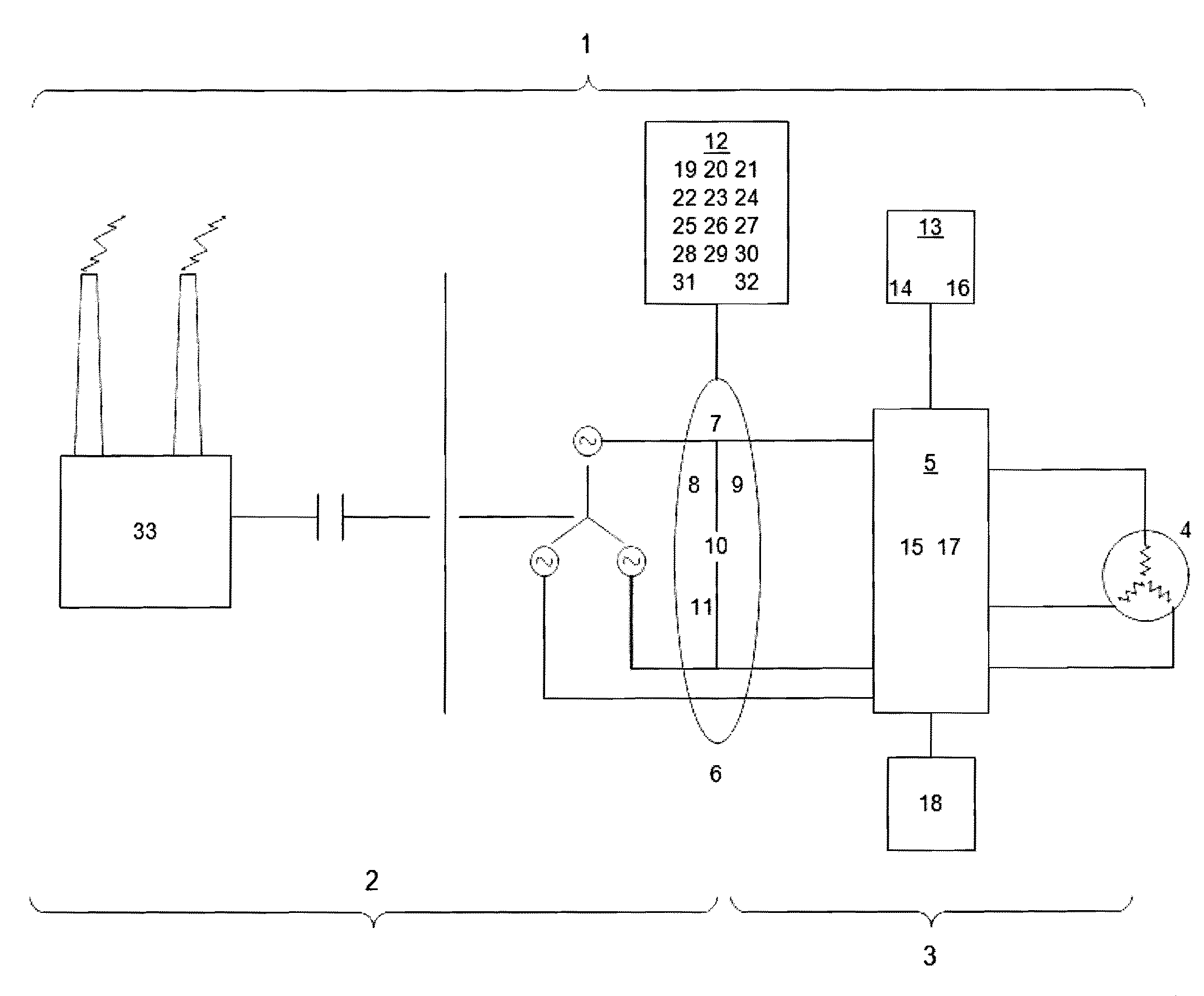
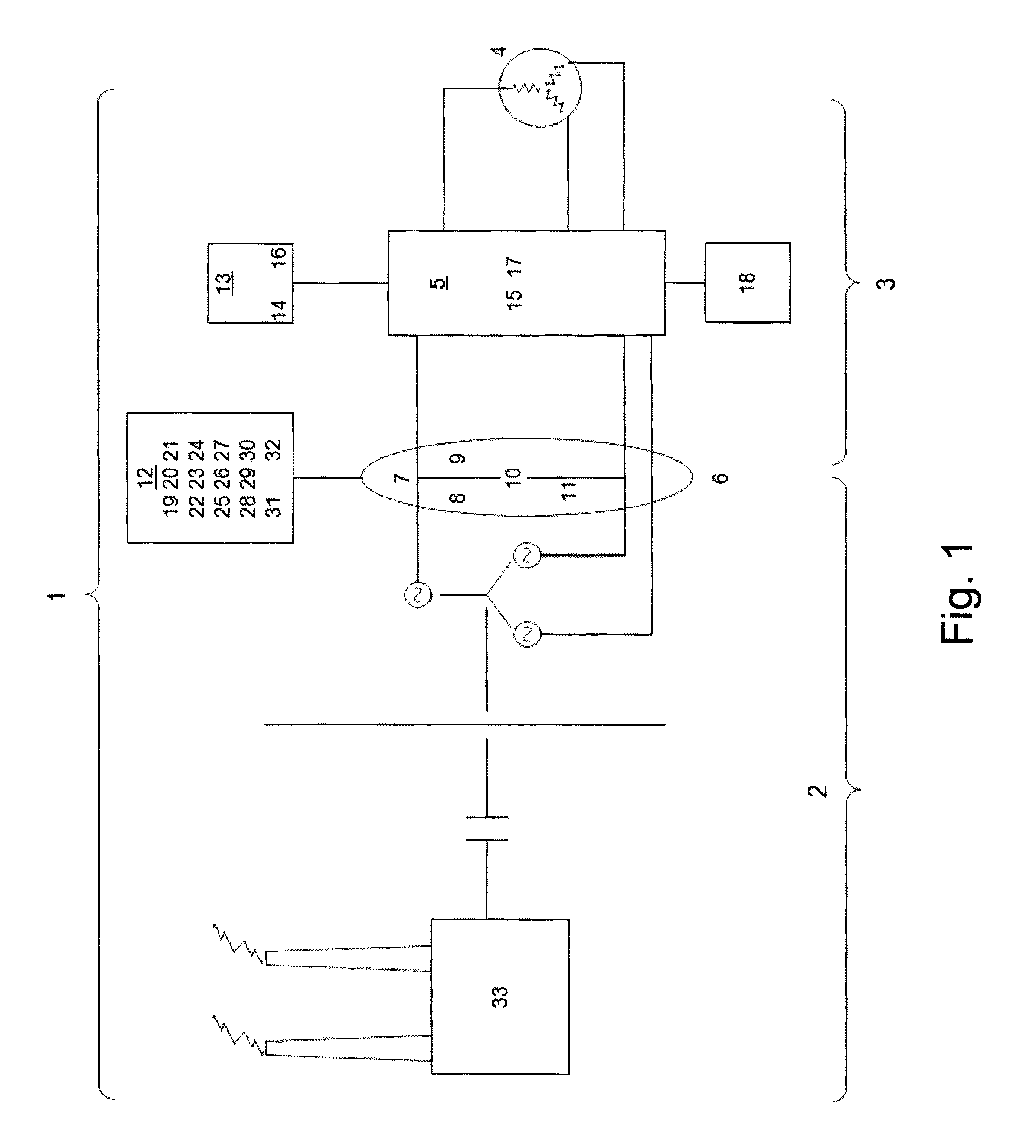
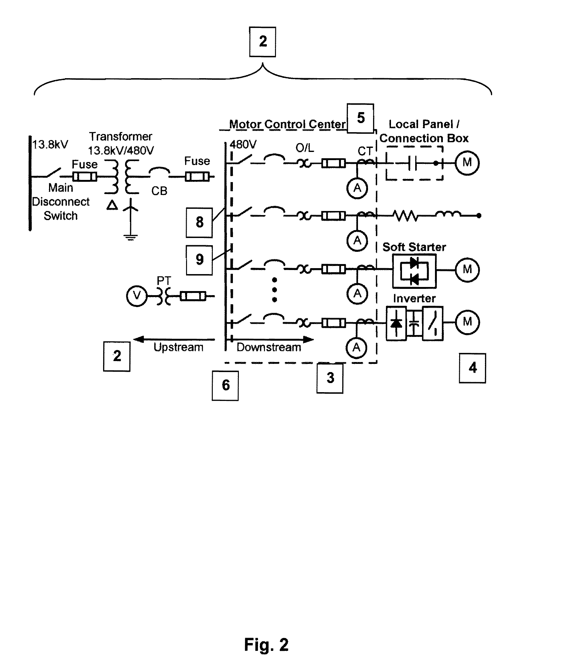
BACKGROUND[0001]The present invention relates to methods and devices to test electric machine circuitry. Specifically it relates to system, through which upstream and downstream circuitry can be tested to detect incipient and existing faults.[0002]Electric machines, such as electric motors or the like play a critical role in our society. They often provide operations which many times cannot be interrupted. Continued, uninterrupted operation is often critical to the devices for which they are a component. Oftentimes, they cannot be permitted to fail. Unfortunately, their operation can at times be attended by corroded contacts and weakened connections.[0003]High-resistance(R) connections can occur due to poor contact at the joint of any device connected between the source and load in an electrical distribution system of an industrial facility as shown in FIG. 1. As shown thermographically in FIG. 3, corroded contacts can even be a source of danger. The location of poor contacts may al...

Claims


Application Information

Patent Timeline
IPC IPC(8): G01R31/00
CPCG01R31/343G01R31/04G01R31/66
Inventor WIEDENBRUG, ERNESTOLEE, SANG BIN
Owner SKF USA INC
Learn More