RF power amplifier system with impedance modulation

a power amplifier and impedance modulation technology, applied in the direction of high frequency amplifiers, gain control, transmission, etc., can solve the problems of significant net decrease in power consumption of the rf pa circuit, undesirable wide spectral occupancy, power wasted during the off, etc., to improve the efficiency of the rf pa

Active Publication Date: 2010-03-11
QUANTANCE
View PDF47 Cites 13 Cited by
  • Summary
  • Abstract
  • Description
  • Claims
  • Application Information

AI Technical Summary

Benefits of technology

[0009]Embodiments of the present invention include a power amplifier controller circuit that controls an adjustable impedance matching network at the output of a power amplifier to improve the efficiency of the RF PA. In a first embodiment of the present invention, the PA controller circuit comprises an amplitude control loop that determines an amplitude correction signal (also referred to herein as

Problems solved by technology

RF PAs are one of the most significant sources of power consumption in these electronic devices, and their efficiency has a significant impact on the battery life on these portable electronic devices.
Since the RF spectrum is shared amongst users of the cellular telephone, a wide spectral occupancy is undesirable.
This typically results in power bein

Method used


Image

  • RF power amplifier system with impedance modulation
  • RF power amplifier system with impedance modulation
  • RF power amplifier system with impedance modulation

Examples


first embodiment

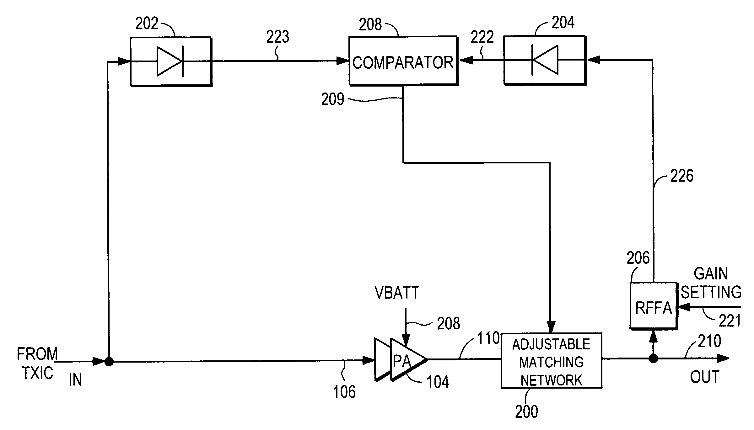
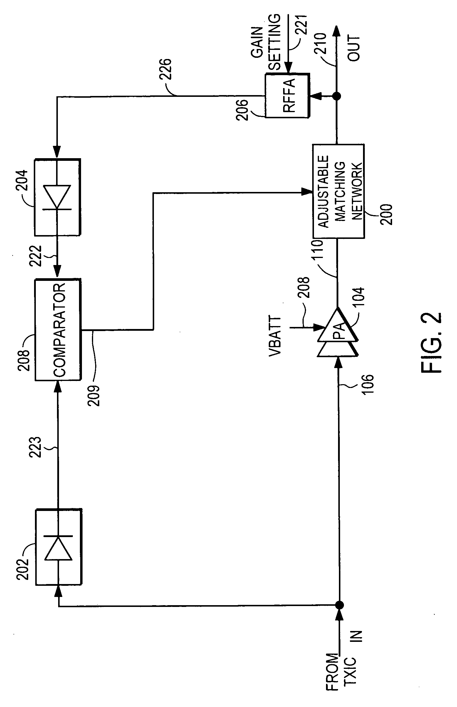
[0031]FIG. 2 illustrates an RF PA controller circuit, according to the present invention. A power amplifier (PA) 104 receives and amplifies an input signal 106 provided from a transmitter IC (TXIC) to the power amplifier 104, and generates an output signal 110. The RF PA controller circuit, comprised of variable attenuator (RFFA (RF Feedback Attenuator)) 206, amplitude detectors 202, 204, comparator 208, and adjustable matching network 200, controls the adjustable matching network 200 based upon an amplitude correction signal (also referred to as amplitude error signal) 209, so that PA 104 may operate in an efficient manner. PA 104 is powered by a supply voltage VBATT 208.

[0032]The PA controller circuit includes an amplitude control loop which determines the amplitude correction signal 209, which is indicative of the amplitude difference between the amplitude of the input signal 106 and the attenuated amplitude 226 of the output signal 210. Comparator 208 receives the amplitude 223 ...

second embodiment

[0034]FIG. 3 illustrates an RF PA controller circuit, according to the present invention. The RF PA controller circuit of FIG. 3 is substantially the same as the RF PA controller circuit of FIG. 2, except that a power supply 310 and a control split module 300 are added. Battery voltage VBATT 208 powers the power supply 310, which provides a controlled supply voltage 308 to the PA 104. When the PA 104 is operating at or near compression, the supply voltage 308 to the PA 104 can vary the PA output 210 amplitude. Thus, the amplitude control loop may additionally correct for PA amplitude errors by adjusting this PA supply voltage 308. Since the PA supply voltage 308 may be typically supplied by an efficient switching regulator, the PA 104 can operate with high efficiency.

[0035]Control split module 300 apportions higher frequency components 302 of the amplitude correction signal 209 to control the adjustable matching network 200, and lower frequency components 309 of the amplitude correc...

third embodiment

[0037]FIGS. 5A, 5B and 5C illustrate variations of an RF PA controller circuit, according to the present invention. In this embodiment, the amplitude correction signal 209 is split by control split module 500 into two or more signals, with one signal 302 controlling the adjustable matching network 200 and at least one other signal controlling a gain adjustment element within the amplitude correction loop In the embodiments of FIGS. 5A, 5B, and 5C, the amplitude control loop may control the adjustable matching network 200 such that the PA 104 operates in both a compressed region and a linear region.

[0038]In the example of FIG. 5A, a variable gain amplifier (VGA) 502 is added as such gain adjustment element to vary the amplitude of the RF input signal 106 for input 506 to the PA 104. The control split module 500 allows control of both the adjustable matching network 200 and the gain of VGA 502 via signals 302, 504, respectively. The advantage of including VGA 502 in the system is that...


PUM


Abstract

A power amplifier controller circuit controls an adjustable impedance matching network at the output of a power amplifier to vary its load line to improve the efficiency of the RF PA. The PA controller circuit comprises an amplitude control loop that determines an amplitude correction signal. The amplitude loop is configured to control or correct for distortion from the adjustable matching network based upon the amplitude correction signal.

Description

CROSS-REFERENCE TO RELATED APPLICATION[0001]This application claims priority under 35 U.S.C. §119(e) from U.S. Provisional Patent Application No. 61 / 095,605, entitled “RF Power Amplifier Controller Circuit with Impedance Modulation,” filed on Sep. 9, 2008, the subject matter of which is incorporated by reference herein in its entirety.BACKGROUND OF THE INVENTION[0002]1. Field of the Invention[0003]The present invention relates to a circuit for controlling RF PAs (Radio Frequency Power Amplifiers), and more specifically, to an RF PA controller circuit that includes control of an adjustable matching network at the output of the PA.[0004]2. Description of the Related Arts[0005]RF (Radio Frequency) transmitters and RF power amplifiers are widely used in portable electronic devices such as cellular phones, laptop computers, and other electronic devices. RF transmitters and RF power amplifiers are used in these devices to amplify and transmit the RF signals remotely. RF PAs are one of the...

Claims


Application Information

Patent Timeline
IPC IPC(8): H03F1/00
CPCH03F1/0227H03F1/0238H03F1/3247H03F1/56H03F3/19H04B1/0458H03F2200/387H03F2200/78H03F2200/99H03F2201/3231H03F3/24
Inventor DROGI, SERGE FRANCOISVINAYAK, VIKAS
Owner QUANTANCE
Why Eureka
Try Eureka