Optical communication device, method and system

a communication device and optical communication technology, applied in the field of optical communication devices, can solve the problems of limited market penetration, large and expensive solar powered sensors, and limited application,

Active Publication Date: 2010-03-11
LUTRON TECH CO LLC
View PDF98 Cites 95 Cited by
  • Summary
  • Abstract
  • Description
  • Claims
  • Application Information

AI Technical Summary

Benefits of technology

[0021]Optionally, an identification tag can receive commands from the reader in addition to transmitting data to the reader, which can among other things, prevent the tag from inadvertently transmitting. The light from the reader can be modulated between two different optical power levels by the data that forms a command, which is converted to an electrical signal by the LED in the tag and decoded by the controller IC. The electrical signal can be

Problems solved by technology

Solar powered sensors are currently large and expensive, which limits their application.
The penetration into the marketplace is growing but has been limited by the cost of the tag, which includes an antennae that is necessary for RF communication.
Additionally the chip must be mounted and connected to the antennae, which increases cost and reduces reliability.
Other well known limitations of RFID tags include disturbances due to metal, water, and electromagnetic interference (EMI), and cross talk between tags.
In harsh environments and along conveyor belts, for instance, with closely spaced tagged items, RFID tags can be unreliable.
For very high volume applications,

Method used


Image

  • Optical communication device, method and system
  • Optical communication device, method and system
  • Optical communication device, method and system

Examples


Embodiment Construction

[0041]Optical communication devices, systems and methods are disclosed that utilize a single optical device to transmit and receive data. Further, this single optical device can also be used to power the device in addition to providing for communications to external devices.

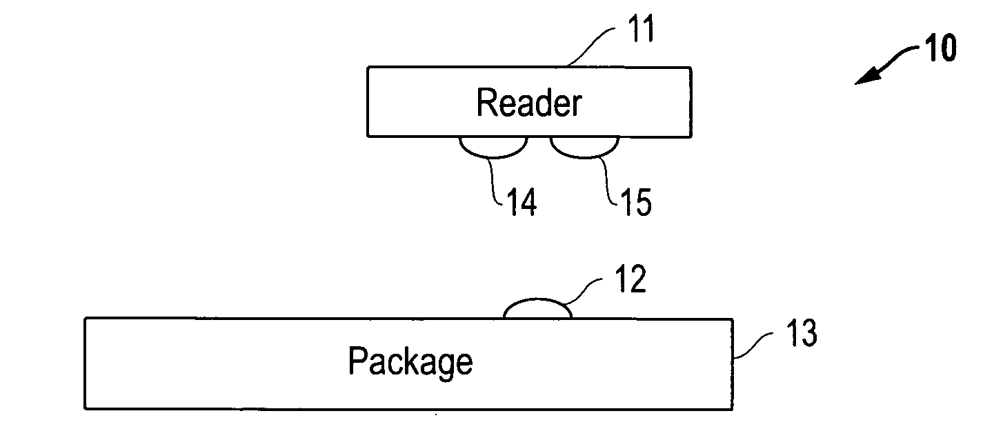
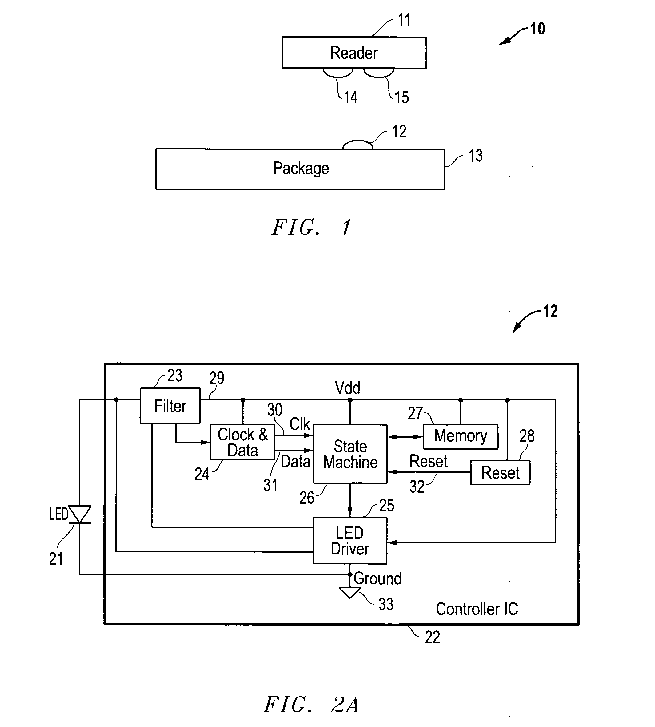
[0042]Turning now to the drawings, FIG. 1 illustrates one example of an optical identification tag system 10, which includes a reader 11 and a tag 12 attached to a package 13. It is understood that system 10 can operate with any frequency light including and preferentially near infrared light (e.g., wavelengths of about 0.7 to 1.0 micrometers). The reader 11 includes an optical transmitter 14 and optical receiver 15 that provide power to and communicate with the tag 12. The reader 11 is powered by a battery or an electrical outlet and, if desired, can be optimized to produce a maximum amount of transmitted optical power to the tag 12 and can be optimized to receive a minimum amount of power. This enables the maxi...


PUM


Abstract

Exemplary optical communication devices are described which, in certain embodiments, derive power optically from and communicate optically to a reading device. The communication devices may also receive data from modulated light from the reading device to achieve a bi-directional optical communication link between the self-powered optical communication device and the reading device. In some embodiments, the communication device is powered by ambient light, such as sunlight, captures data from a sensor, and communicates the stored data some time later to a reading device. In some embodiments, the communication device is powered locally and communicates through air, optical fiber, or other medium with another communication device.

Description

RELATED APPLICATIONS[0001]This application claims priority to the following co-pending provisional application: Provisional Application Ser. No. 61 / 094,595 entitled “OPTICAL COMMUNICATION DEVICE, METHOD AND SYSTEM,” which was filed on Sep. 5, 2008.TECHNICAL FIELD OF THE INVENTION[0002]This invention relates to optical communication devices and, more particularly, to self-powered identification and / or data tags.BACKGROUND[0003]Optical communication devices are used in a variety of applications including, but certainly not limited to self powered identification and data tags, infrared wireless and fiber optic transceivers, and solar powered sensors. Optical identification and data tags have certain advantages over Radio Frequency Identification (RFID) and data tags. Solar powered sensors are currently large and expensive, which limits their application.[0004]Self powered radio frequency identification (RFID) tags have been used for years for identifying items with a unique identificat...

Claims


Application Information

Patent Timeline
IPC IPC(8): H04B10/10H04B10/02H04B10/43
CPCH04B10/807H04B10/1143
Inventor KNAPP, DAVID J.
Owner LUTRON TECH CO LLC
Why Eureka
Try Eureka