
Incubation system with low temperature enclosure

Active Publication Date: 2010-03-11
BIOMERIEUX INC
View PDF9 Cites 29 Cited by
  • Summary
  • Abstract
  • Description
  • Claims
  • Application Information

AI Technical Summary

Benefits of technology

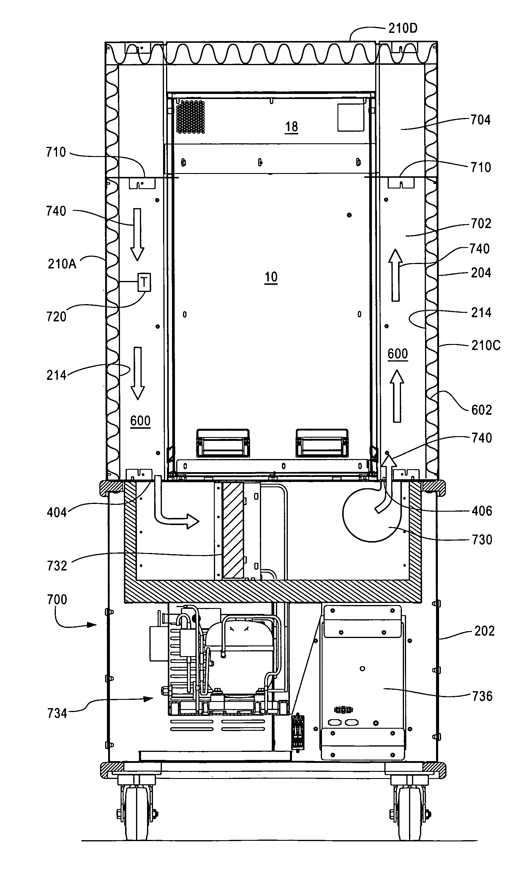
[0018]In a preferred configuration, the enclosure includes seals making a substantially air-tight seal between the enclosure and the base and between the enclosure and the incubator in the area surrounding the void in the enclosure. The seals prevent introduction of ambient air into the region between the enclosure and the incubator. This design allows for closed loop circulation of cool air to and from the incubation enclosure and minimizes formation of condensation inside the incubation enclosure.
[0019]In another possible configuration, the incubator includes a top portion and an electronics module positioned in the top portion of the incubator. The insulated enclosure is constructed and arranged into a first or lower compartment surrounding the incubator and a second or upper compartment surrounding the top portion of the incubator. The two compartments are separated from each other (e.g., using baffles), such that air from the system supplying cold air does not enter the upper compartment. This design prevents any possible damage to the electronics due to condensation as the cool air is not circulated to the upper compartment.

Problems solved by technology

owever, under normal laboratory working conditions in which the laboratory and incubator is maintained in a room temperature (20-22° C.) ambient environment, some incubators are not capable of maintaining a stable incubation range of 20-25° C. Simply leaving the specimen to be incubated out on the laboratory bench at “room temperature” is of course not acceptable, as the environment is not reliably temperature controlled (e.g., a window may be left open, the air conditioning system may not work properly, the heating system may be turned down at night or over the weekend to save energy, etc.).
However, this approach does not provide an efficient work environment, because the walk-in environmental chamber is typically not conveniently located, e.g., it is down the hall or on another floor.
The walk-in environmental chamber is typically in a separate location away from the other incubators, thus making use of the incubators in the environmental chamber more inconvenient and inefficient.
An alternative approach that has been considered is to cool the entire laboratory space where the incubators are located down to say 10-13 degrees C. However, this is not a comfortable work environment for laboratory technicians, as they have to bundle up to stay warm and contend with working with cold hands.
This unit was considered to be too noisy for the laboratory environment due to the high blower RPMs.
The 220 VAC power supply the unit required was not easily adaptable to most laboratories either.
The product was a commercial failure for these and other reasons, and supposedly only 1 or 2 instruments were ever sold.

Method used


Image

  • Incubation system with low temperature enclosure
  • Incubation system with low temperature enclosure
  • Incubation system with low temperature enclosure

Examples


Embodiment Construction

[0037]Overview

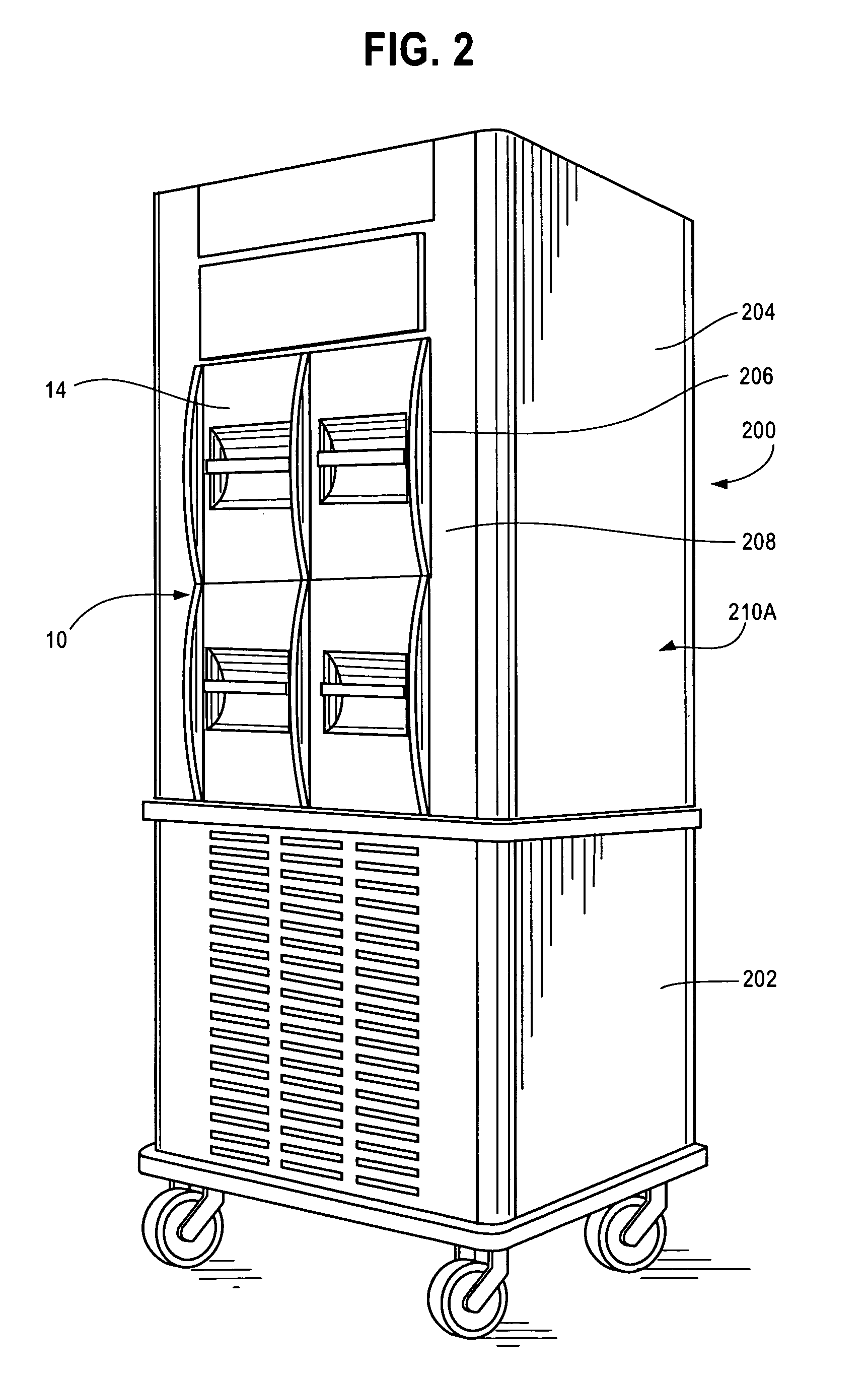
[0038]Referring now to the Figures, FIG. 2 is a perspective view of an incubation system 200 according to one embodiment of this invention. The system 200 includes an incubator 10 (such as for example the incubator of FIG. 1), a base or cart 202 containing a machine generating a supply of cold air, and an enclosure 204 surrounding the incubator 10. The enclosure 204 is typically, but not necessarily, insulated. That is, the enclosure has insulation added to the shell or skin forming the enclosure 204 and / or the enclosure 204 is made from a material and / or thickness such that it has intrinsic insulation properties without addition of extra insulation.

[0039]The incubator 10 and enclosure 204 are placed on the top of the base 202. The base 202 serves as a mobile base for the enclosure 204 and incubator 10 to sit on, while also housing a refrigeration machine 700 (shown in FIG. 7) generating cold air, and the power supply for the refrigeration machine. The power supply adj...


PUM

PropertyMeasurementUnit
Temperatureaaaaaaaaaa

Abstract

An incubator is fitted with an enclosure which surrounds the incubator. A cold air generation system supplies relatively cold air to a space formed between enclosure and the incubator. The system supplying the cold air can be embodied in a cart or base upon which the incubator sits. The enclosure is also placed on the base in a manner such that it substantially envelops the incubator. The top of the cart has openings for egress of cold air and return of air so that air may circulate in a closed loop. The incubator, cold air supply system and enclosure present a solution for incubating samples in a nominal 20-25° C. temperature environment. The enclosure, which is preferably insulated, may include a void or opening which exposes doors or other access device of the incubator, allowing direct access to the samples in the incubator while the rest of the incubator is enveloped by the enclosure.

Description

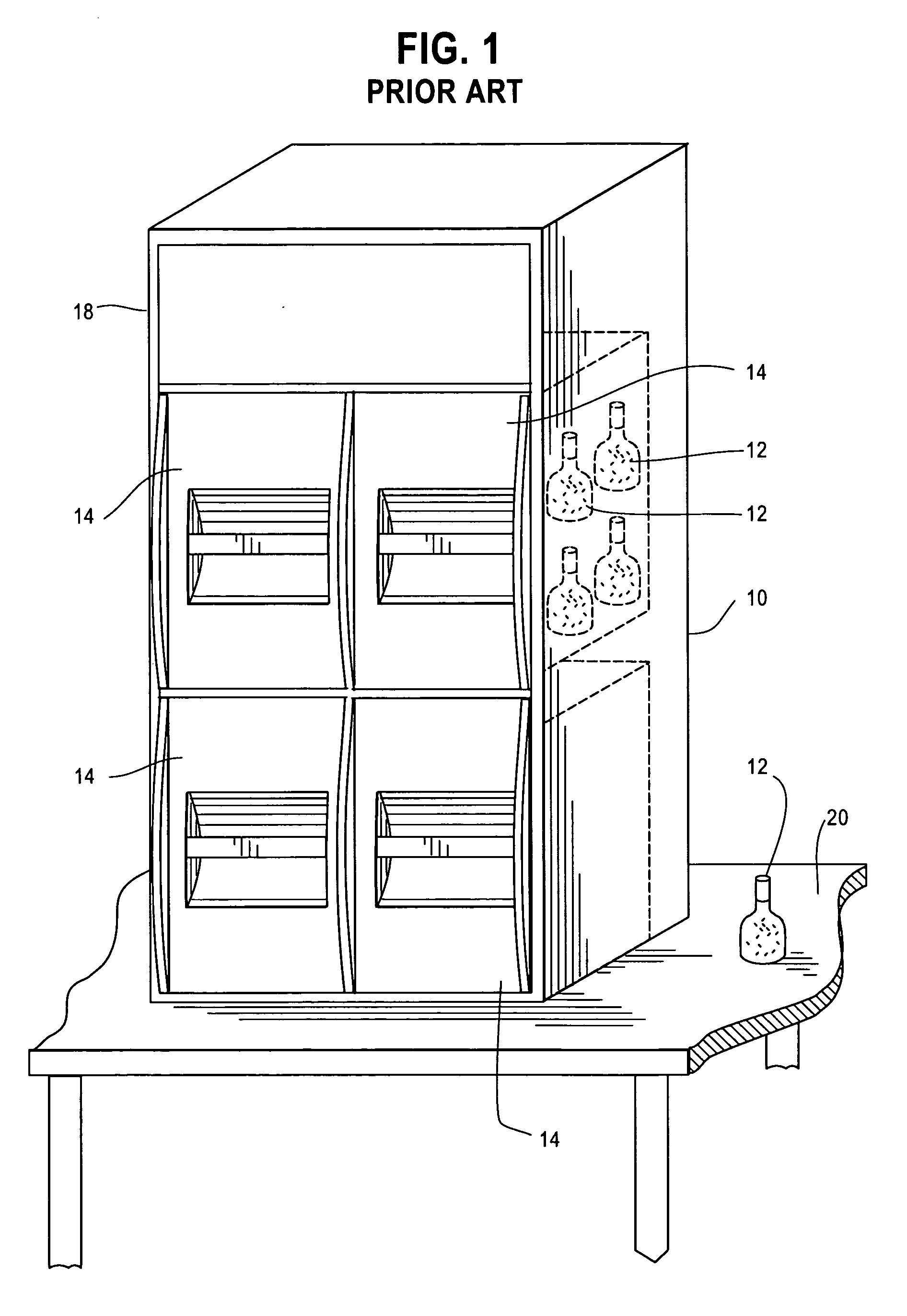
BACKGROUND[0001]1. Field[0002]This invention relates to the field of incubators, and more particularly to an incubator that is designed to maintain an incubation temperature that is close to room temperature, e.g., between 20 and 25° C.[0003]2. Description of Related Art[0004]Incubators for incubating biological samples, such as human blood samples placed in a bottle or like container, are known in the art. FIG. 1 shows one such incubator 10, marketed by the applicants' assignee bioMerieux, Inc. as the BacT / Alert 3D™ incubation system. The incubator 10 is designed to incubate blood collection bottles 12 which contain a culture medium. The incubator has drawers 14 which pull out from the rest of the incubator to allow the user to insert and remove the bottles 12 from the incubator 10.[0005]The incubator further includes optical sensors (not shown) which read the bottles 12 to determine whether a reaction has occurred between the sample in the bottles and a growth medium in the bottle...

Claims


Application Information

Patent Timeline
IPC IPC(8): C12M1/00
CPCC12M41/14Y10T29/49716B23P6/00
Inventor FANNING, MARK J.YAM, JACKYROBBINS, DAVID M.KETSENBURG, KEVIN G.BISHOP, JAMES C.
Owner BIOMERIEUX INC
Learn More