In-line process measurement systems and methods

a technology of process measurement and measurement results, applied in the direction of optical radiation measurement, interferometric spectrometry, instruments, etc., can solve the problems of unacceptably inaccurate estimation, inability to adequately measure the data relating to one, and difficulty in simple measurement of light intensity to be useful information, so as to improve the signal-to-noise ratio of measurement results and improve the accuracy and precision of material analysis

Active Publication Date: 2010-03-25
HALLIBURTON ENERGY SERVICES INC
View PDF103 Cites 73 Cited by
  • Summary
  • Abstract
  • Description
  • Claims
  • Application Information

AI Technical Summary

Benefits of technology

[0044]The present disclosure provides a further advancement of prior multivariate optical analysis systems, such advancement resulting in an improvement in signal-to-noise...

Problems solved by technology

In general, a simple measurement of light intensity is difficult to convert to useful information because it likely contains interfering data.
It is often impossible to adequately measure the data relating to one of these factors since the contribution of the other factors is unknown.
Depending on the circumstances, however, the estimate may be unacceptably inaccurate, since factors other th...

Method used


Image

  • In-line process measurement systems and methods
  • In-line process measurement systems and methods
  • In-line process measurement systems and methods

Examples


example i

System I

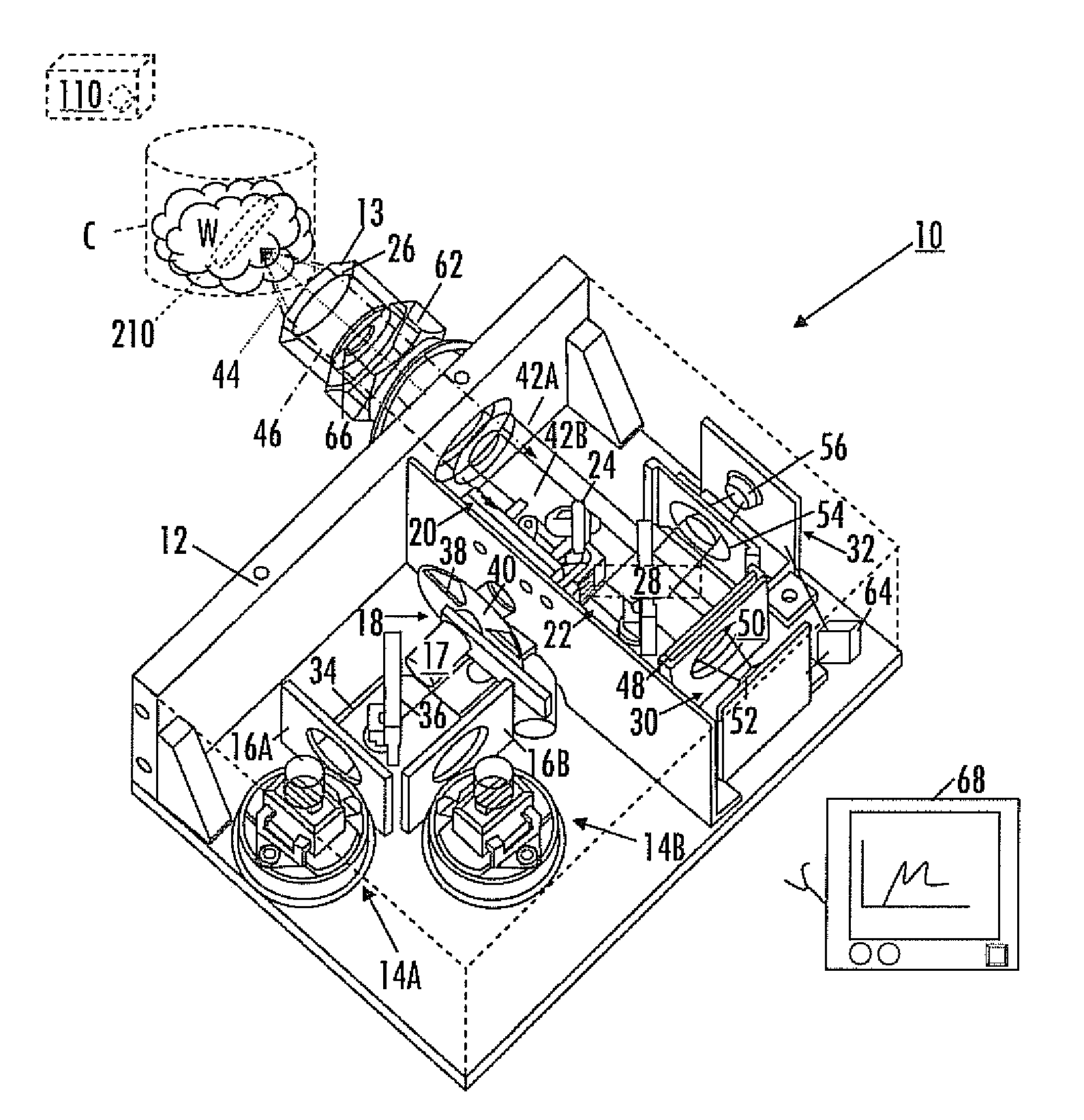
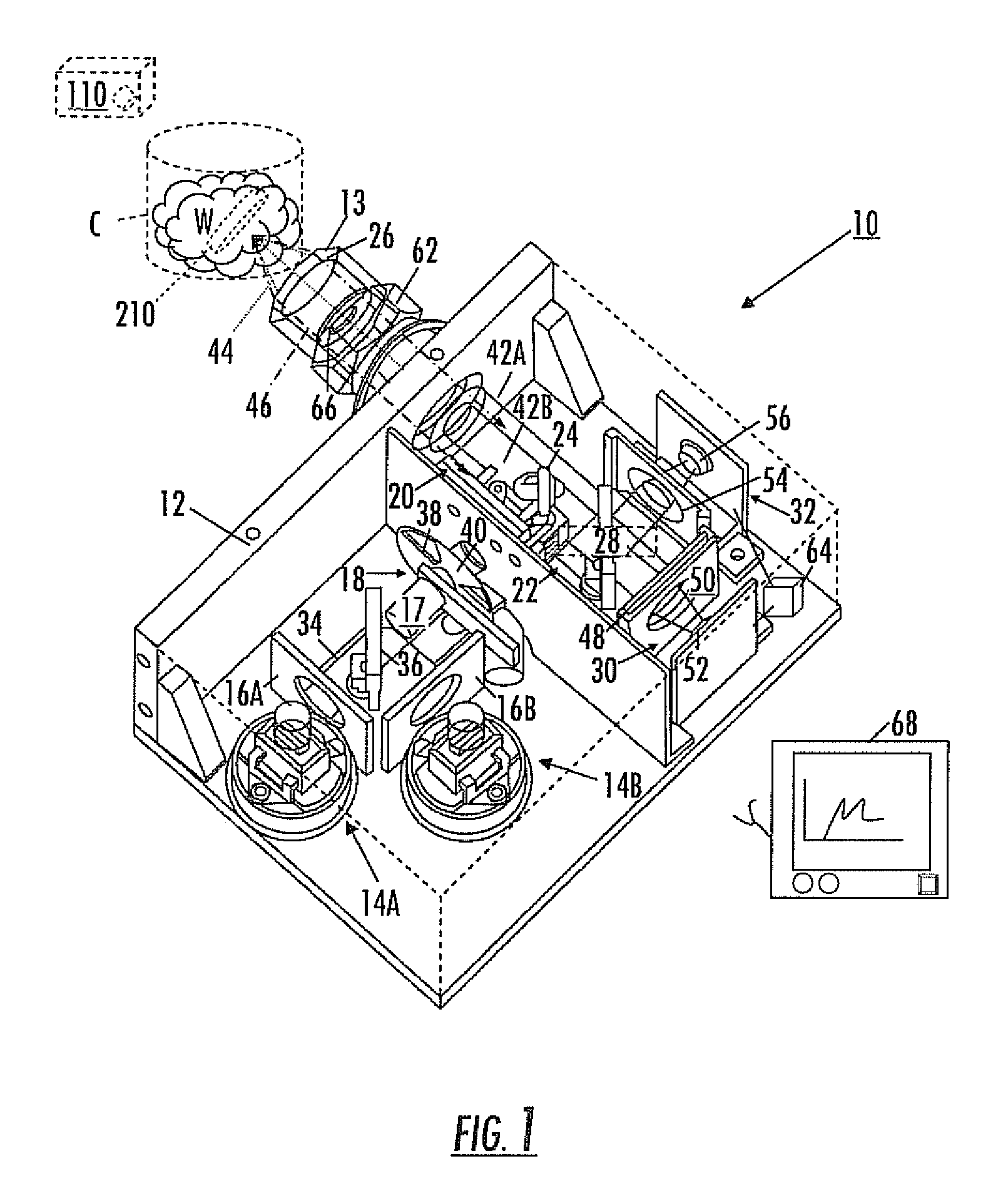
[0143]A system similar to the optical analysis system 10 shown in the figures was constructed and used to make static measurements on aspirin / lactose.

[0144]System I Components:

Illumination: 20 W Gilway lamp

Spectral elements: 5 mm D2O, 5 mm Germanium

Optical window: none

Detector: PbS detector from New England Photoconductor

MOE: specific to test conditions.

[0145]Procedure and Results of Static Testing Using System I:

[0146]A powdered sample with a known composition was placed in a dish and the system light beam was focused on the powder. The output of the detectors was monitored and recorded. Aspirin / lactose samples covering the range of 100% aspirin to 100% lactose were tested.

example ii

System II

[0147]A system similar to the optical analysis system 10 shown in the figures was constructed and used to make dynamic measurements on aspirin / lactose.

[0148]System II Components:

Illumination: 20 W Gilway lamp

Spectral elements: 5 mm D2O, 5 mm Germanium

Optical window: sapphire window

Detector: PbS detector from New England Photoconductor

MOE: specific to test conditions.

[0149]Procedure and Results of Dynamic Testing Using System II:

[0150]The Aspirin / Lactose testing was made on a mixer bowl containing lactose and the system measured as aspirin was added to the system and mixed. Specifically, lactose powder was placed in the bowl of a mixer and the measurement system was attached the bowl using a Swagelok® brand fitting. A sapphire window was used to contain the powder in the bowl and allow the system to interrogate the powder. With the mixer turning, known amounts of aspirin were added and the system output signal was monitored and recorded. Aspirin was added in several allotmen...

example iii

System III

[0151]A system similar to the optical analysis system 10 shown in the figures was constructed and used to make static measurements on aspirin / lactose.

[0152]System III Components:

Illumination: 5 W Gilway lamp

Spectral elements: 5 mm D2O, 5 mm Germanium

Optical window: none

Detector: PbS detector from New England Photoconductor

MOE: specific to test conditions.

[0153]Procedure and Results of Dynamic Testing Using System III:

[0154]Similar to the examples above.


PUM


Abstract

A method of using multivariate optical computing in real-time to collect instantaneous data about a process stream includes installing an optical analysis system proximate a process line, the process line being configured to move a material past a window of the optical analysis system; illuminating a portion of the material with a light from the optical analysis system; directing the light carrying information about the portion through at least one multivariate optical element in the optical analysis system to produce an instantaneous measurement result about the portion; and continuously averaging the instantaneous measurement result over a period of time to determine an overall measurement signal of the material.

Description

TECHNICAL FIELD[0001]Provided herein are in-line process measurement systems and methods for achieving reliable, instantaneous measurements of various product parameters. The measurement system uses multivariate optical computing, using light to illuminate a portion of the target product and then directing the light through a multivariate optical element to a detector, to collect data instantaneously about the real-time product characteristics. The instantaneously collected data represents a mathematical relationship (e.g., a ratio) of signals produced by light that is reflected from the illuminated product. Such ratios are continuously averaged over time to provide a continuous measurement of product and / or process conditions of interest. In response to these continuous, real-time measurements, process conditions and / or equipment settings may be automatically modified, as necessary, to achieve the desired results.BACKGROUND OF THE DISCLOSUREPrinciples of Spectroscopic Analysis[0002...

Claims


Application Information

Patent Timeline
IPC IPC(8): G01J3/45G01J3/00
CPCG01J3/02G01J3/0208G01J3/0232G01J3/42G01J3/0264G01J3/0291G01J3/0235G01N21/31G01N2021/151
Inventor PERKINS, DAVID L.FREESE, ROBERT P.BLACKBURN, JOHN C.JAMES, JONATHAN H.
Owner HALLIBURTON ENERGY SERVICES INC
Why Eureka
Try Eureka