Magnetic disk substrate and magnetic disk

a magnetic disk and substrate technology, applied in the field of substrates, can solve the problems of substrate material itself being damaged, foreign substances contaminating the surface, failure of hdd,

Inactive Publication Date: 2010-04-01
HOYA CORP +1
View PDF10 Cites 10 Cited by
  • Summary
  • Abstract
  • Description
  • Claims
  • Application Information

AI Technical Summary

Benefits of technology

[0018]Further, an offset film preferably may be formed on the second main surface for offsetting a film stress generated when the laminated film is formed on the first main surface.
[0019]In addition, the magnetic disk substrate may be made of a multi-component glass, and an elution preventing film preferably may be formed on the second main surface for preventing elution of ions forming the multi-component glass to the surface of the magnetic disk substrate.

Problems solved by technology

Accordingly, if a minute uneven defect exists on the magnetic disk, the head is brought into contact with the magnetic disk, thus causing failure of the HDD.
This minute uneven defect is a damage-based defect such that a disk substrate material itself is damaged in some way, or a foreign substance-based defect such as residue of abrasive grains due to polishing carried out for improving the flatness of a magnetic disk substrate or a foreign substance that adheres / remains in cleaning, drying, or the like.
Particularly, the latter is caused by the fact that particles / contaminants that adhere to an end face of a glass substrate during end face processing are released from the end face and adhere again to main surfaces of the glass substrate in a subsequent cleaning process.
However, if residue of abrasive grains due to polishing of both main surfaces of the one-side magnetic disk substrate or foreign substances that adhere in cleaning, drying, or the like (hereinafter collectively referred to as “foreign substances”) exist on the surface B, when cleaning the substrate before stacking a magnetic layer and so on on the surface A, there is a possibility that (1) the foreign substances contaminate the surface A due to re-adhesion thereof during cleaning or (2) the foreign substances contaminate a cleaning apparatus itself.
Further, with respect to an obtained magnetic disk, it may happen that the foreign substances on the surface B are scattered due to the rotation of the magnetic disk and adhere to a magnetic head in a seek test on the surface A, thereby causing a read / write error.
Further, in an actual inspection process of the magnetic disk formed with the magnetic layer and so on, there is a case where an inspection head is also provided for the surface B and, in this case, if the foreign substances remain in large numbers on the surface B, there is a possibility that the inspection head is contaminated or damaged when the inspection head is in close vicinity to the surface B.

Method used


Image

  • Magnetic disk substrate and magnetic disk
  • Magnetic disk substrate and magnetic disk
  • Magnetic disk substrate and magnetic disk

Examples


example

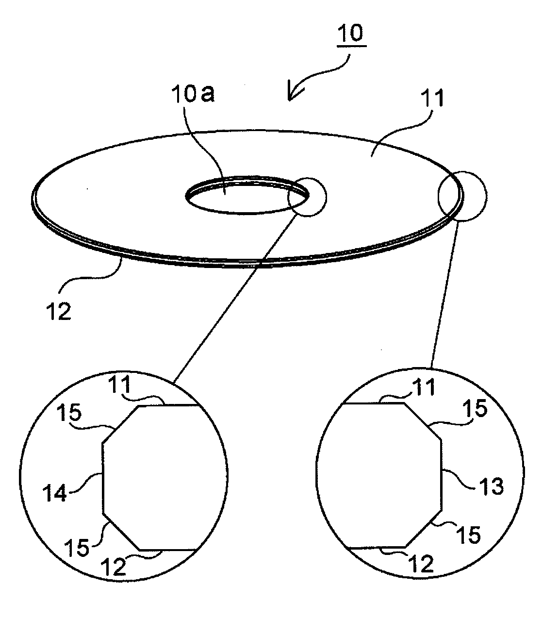
[0078]First, a molten aluminosilicate glass was formed into a disk shape by direct pressing using upper, lower, and drum molds, thereby obtaining an amorphous plate-like glass member (blank). In this event, the diameter of the blank was 66 mm. Then, first lapping was applied to both main surfaces of the blank and then, using a cylindrical core drill, processing (coring) was carried out to form a hole 10a at a central portion of the blank, thereby obtaining an annular glass substrate 10. Then, a chamfering process (chamfered face forming process) was carried out to form chamfered faces 15 at end portions (outer peripheral end portion 13 and inner peripheral end portion 14) and then second lapping was carried out.

[0079]Then, the outer peripheral end portion 13 of the glass substrate 10 was mirror-polished by a brush polishing method. In this event, as polishing abrasive grains, use was made of a slurry (free abrasive grains) containing cerium oxide abrasive grains.

[0080]Then, the mirr...


PUM

PropertyMeasurementUnit
sizesaaaaaaaaaa
sizesaaaaaaaaaa
sizesaaaaaaaaaa

Abstract

In a magnetic disk substrate being annular and having a first and a second main surface, (1) surface roughness measured by an atomic force microscope having a resolution of 256×256 pixels per 2 μm square and/or (2) the number of foreign substances detected to have sizes of 0.1 μm or more and 1.0 μm or less upon detection of scattered light from the magnetic disk substrate when laser light with a wavelength of 405 nm is irradiated with a spot size of 5 μm at a laser power of 25 mW differ/differs between the first and the second main surfaces. Only the first main surface has a surface quality usable as a magnetic recording surface. The number of the foreign substances detected to have the sizes of 0.1 μm or more and 1.0 μm or less upon detection of the scattered light from the magnetic disk substrate when the laser light with the wavelength of 405 nm is irradiated with the spot size of 5 μm at the laser power of 25 mW is 400 or less per 30 cm2 on the second main surface.

Description

[0001]This application is based upon and claims the benefit of priority from Japanese Patent Application No. 2008-247161, filed on Sep. 26, 2008, the disclosure of which is incorporated herein in its entirety by reference.BACKGROUND OF THE INVENTION[0002]This invention relates to a substrate for a magnetic disk (hereinafter referred to as a “magnetic disk substrate”) and a magnetic disk.[0003]As a magnetic recording medium adapted to be mounted in a hard disk drive (HDD), there is a magnetic disk. The magnetic disk is fabricated by stacking a magnetic layer and a protective layer over a substrate in which a NiP film is coated on a metal plate made of an aluminum-magnesium alloy or the like, a glass substrate, or a ceramic substrate. In order to meet the needs of markets and with the development of the microfabrication technique in recent years, the reduction in size and the increase in density of magnetic disks have advanced and, nowadays, the storage capacity reaches up to, for exa...

Claims


Application Information

Patent Timeline
Patent Type & Authority Applications(United States)
IPC IPC(8): G11B5/706
CPCG11B5/82G11B5/7315G11B5/73921
Inventor NISHIMORI, KENICHITOMONAGA, TADASHI
Owner HOYA CORP
Why Eureka
Try Eureka