Reciprocating compressor

Inactive Publication Date: 2010-04-08
HOERBIGER KOMPRESSORTECHNIK HLDG GMBH
View PDF10 Cites 15 Cited by
  • Summary
  • Abstract
  • Description
  • Claims
  • Application Information

AI Technical Summary

Benefits of technology

[0014]To accelerate and/or brake the actuation device's movement additional spring elements may be provided, allowing for the relief of stress on the electric motor drive with appropriate adjusting.
[0015]In a further preferred embodiment of the invention switching elements for dynamic braking and for temporary storage and reuse of the electric energy recovered therefrom may be provided in the electric drive of the electric motor. The energy may preferably be stored temporarily in capacitors, during the process of which the generated and stored current may be used either for the next actuation process at the same valve or at a different suction valve of the compressor. This way, the energy consumption

Problems solved by technology

The greater this counteracting force is, the later the respective suction valve in the compression stroke closes, resulting in the reduction of the capacity.
Furthermore, reciprocating compressors with an electrically operated reverse flow control of

Method used


Image

  • Reciprocating compressor
  • Reciprocating compressor
  • Reciprocating compressor

Examples


Embodiment Construction

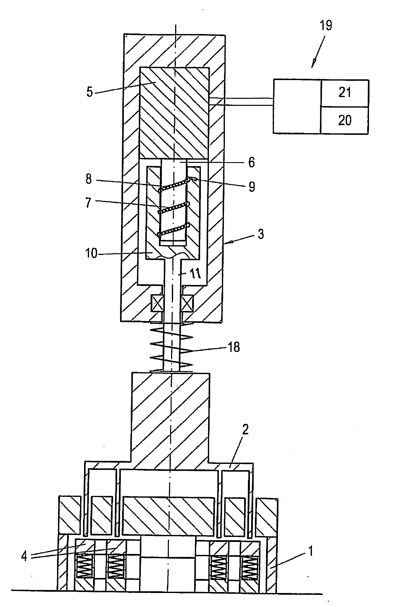
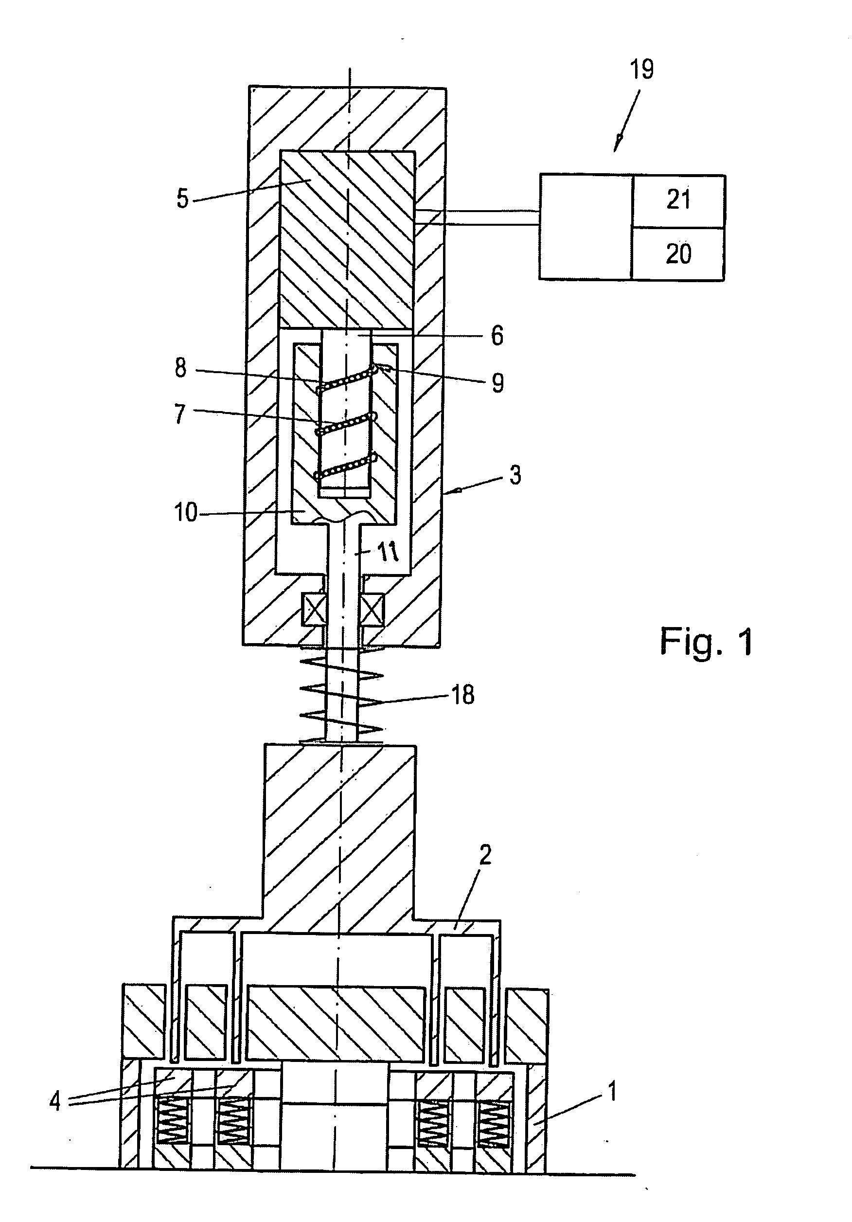
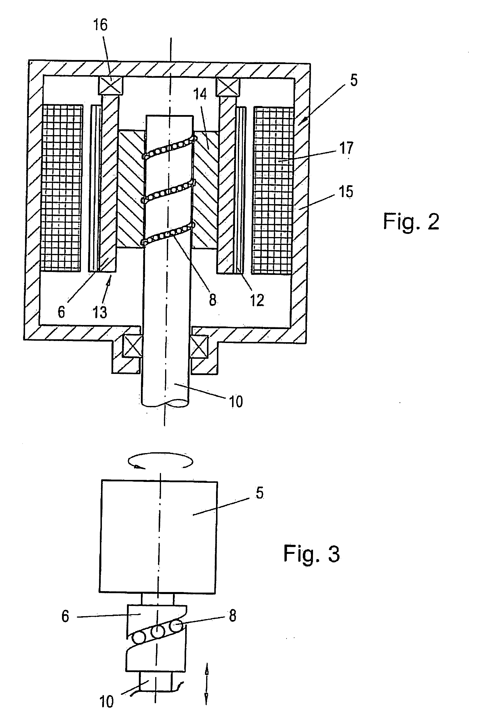
[0021]According to FIG. 1, a reciprocating compressor—not further shown—comprises a valve unloader 2 arranged at an automatically acting suction valve 1 of the compressor, said valve unloader holding open two ring-shaped sealing elements 4 of the suction valve 1 over a controllable portion of the compressor's cycle by means of an electrically operated actuation device 3. For this purpose, the actuation device 3 comprises as drive an electric motor 5, whose driven element 6 (developed here as a central shaft) comprises a guide surface 7 (here circumferential spiral groove) extending in an inclined manner in rotational direction for low-friction rolling elements 8, which on the other hand interact with a counter-guide 9 extending in an inclined manner at a non-rotating lifting element 10, the latter being connected to the valve unloader 2.

[0022]As soon as the electric motor 5 is supplied with current, its driven element 6 rotates, which, in conjunction with the non-rotating lifting el...


PUM


Abstract

In a reciprocating compressor with delivery rate control the actuation device (3) for the valve unloader (2) of the suction valve (1) to be held open comprises as drive an electric motor (5), whose driven element (6) in conjunction with the non-rotating lifting element (10) of the valve unloader (2) and the rolling elements (8) arranged in between forma ball screw drive. This results in a small-dimensioned, precisely to be regulated actuation device (3) with high actuating forces and with high motion dynamic.

Description

BACKGROUND OF THE INVENTION[0001]1. Field of the Invention[0002]The invention relates to a reciprocating compressor with capacity control control, comprising a valve unloader arranged at at least one automatically acting suction valve of the compressor, said valve unloader holding open at least one sealing element of the suction valve over a portion of the compressor's cycle by means of an electrically operated actuation device, as well as a method for controlling the capacity of such a reciprocating compressor.[0003]2. The Prior Art[0004]To control the capacity of reciprocating compressors, preferably running at a constant rotational speed, one frequently resorts to the so-called reverse flow control, in which at least one suction valve per cylinder is kept open over a certain area of the compression stroke. The drag forces exerted by the the gas pushed back through the held-open suction valve close the sealing element of the respective suction valve after overcoming a certain port...

Claims


Application Information

Patent Timeline
IPC IPC(8): F04B7/00
CPCF04B49/243F04B39/00F04B35/04F04B17/04
Inventor SPIEGL, BERNHARDSTEINRUCK, PETER
Owner HOERBIGER KOMPRESSORTECHNIK HLDG GMBH
Why Eureka
Try Eureka