System for use in bone cement preparation and delivery

a technology of bone cement and injection system, which is applied in the field of bone cement injection system, can solve the problems of fractures in the spine and hips, affecting mobility and quality of life, and the medical advances aimed at slowing or arresting bone loss from aging have not provided solutions to this problem, so as to achieve a greater degree of control over the introduction of cement and improve the effect of outcomes

Active Publication Date: 2010-04-15
DFINE INC
View PDF46 Cites 45 Cited by
  • Summary
  • Abstract
  • Description
  • Claims
  • Application Information

AI Technical Summary

Benefits of technology

[0017]There is a general need to provide bone cements and methods for use in treatment of vertebral compression fractures that provide a greater degree of control over introduction of cement and that provide better outcomes. The present invention meets this need and provides several other advantages in a novel and nonobvious manner.

Problems solved by technology

Medical advances aimed at slowing or arresting bone loss from aging have not provided solutions to this problem.
Osteoporosis affects the entire skeleton but most commonly causes fractures in the spine and hip.
Spinal or vertebral fractures also cause other serious side effects, with patients suffering from loss of height, deformity and persistent pain which can significantly impair mobility and quality of life.
Osteoporosis describes a condition of decreased bone mass that leads to fragile bones which are at an increased risk for fractures.
In an osteoporosis bone, the sponge-like cancellous bone has pores or voids that increase in dimension making the bone very fragile.
In an elderly patient, bone resorption can surpass bone formation thus resulting in deterioration of bone density.
Since the PMMA needs to be forced into the cancellous bone, the techniques require high pressures and fairly low viscosity cement.
Since the cortical bone of the targeted vertebra may have a recent fracture, there is the potential of PMMA leakage.
Leakage of PMMA during vertebroplasty can result in very serious complications including compression of adjacent structures that necessitate emergency decompressive surgery.
The exothermic reaction of PMMA carries potential catastrophic consequences if thermal damage were to extend to the dural sac, cord, and nerve roots.
Vertebroplasty patients often return with new pain caused by a new vertebral body fracture.
Leakage of cement into an adjacent disc space during vertebroplasty increases the risk of a new fracture of adjacent vertebral bodies.
Another life-threatening complication of vertebroplasty is pulmonary embolism.
The vapors from PMMA preparation and injection also are cause for concern.
In both higher pressure cement injection (vertebroplasty) and balloon-tamped cementing procedures (kyphoplasty), the methods do not provide for well controlled augmentation of vertebral body height.
Thus, the reduction of a vertebral compression fracture is not optimized or controlled in high pressure balloons as forces of balloon expansion occur in multiple directions.
Expansion of the balloon under high pressures close to cortical bone can fracture the cortical bone, typically the endplates, which can cause regional damage to the cortical bone with the risk of cortical bone necrosis.
Such cortical bone damage is highly undesirable as the endplate and adjacent structures provide nutrients for the disc.
Kyphoplasty also does not provide a distraction mechanism capable of 100% vertebral height restoration.
Further, the kyphoplasty balloons under very high pressure typically apply forces to vertebral endplates within a central region of the cortical bone that may be weak, rather than distributing forces over the endplate.

Method used


Image

  • System for use in bone cement preparation and delivery
  • System for use in bone cement preparation and delivery
  • System for use in bone cement preparation and delivery

Examples


Embodiment Construction

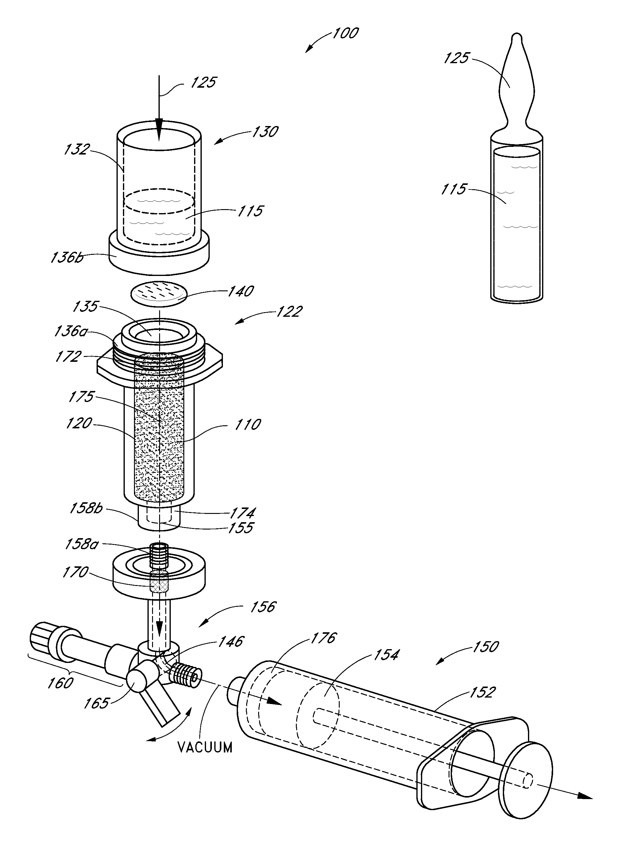
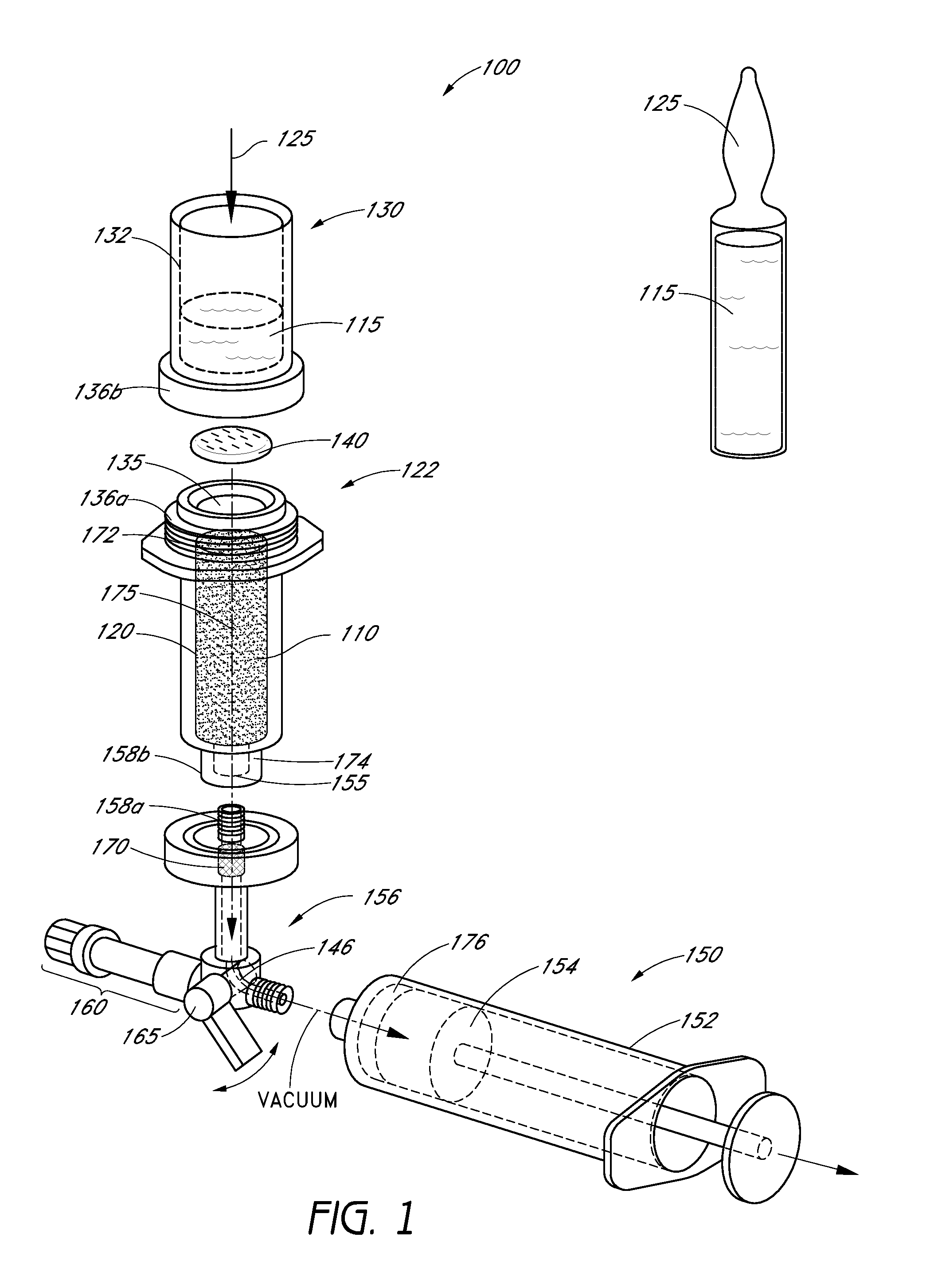
[0031]For purposes of understanding the principles of the invention, reference will now be made to the embodiments illustrated in the drawings and the accompanying text. As background, a vertebroplasty procedure using the system of FIG. 3 could insert parts of the system through a pedicle of a vertebra, or in a parapedicular approach, for accessing the osteoporotic cancellous bone. The initial aspects of the procedure can be similar to a conventional percutaneous vertebroplasty wherein the patient is placed in a prone position on an operating table. The patient is typically under conscious sedation, although general anesthesia is an alternative. The physician injects a local anesthetic (e.g., 1% Lidocaine) into the region overlying the targeted pedicle or pedicles as well as the periosteum of the pedicle(s). Thereafter, the physician can use a scalpel to make a 1 to 5 mm skin incision over each targeted pedicle. Thereafter, an introducer can be advanced through the pedicle into the ...


PUM

PropertyMeasurementUnit
pore sizeaaaaaaaaaa
pore sizeaaaaaaaaaa
pore sizeaaaaaaaaaa

Abstract

A system for use in bone cement preparation can include a chamber for intermixing a liquid monomer and solid polymer components, a container, a vacuum channel, and a filter. The mixing chamber can be configured to hold a non-liquid, polymer powder component of a bone cement. The container can be configured to hold a liquid component of the bone cement. The system can have a first interface disposed between the mixing chamber and the container and a second interface disposed between the mixing chamber and the vacuum channel. The second interface can to receive and position the filter between the mixing chamber and the vacuum channel. The vacuum channel can direct a partial vacuum to draw the liquid component from the container into the non-liquid component in the mixing chamber to intermix the components and to thereby provide a settable bone cement

Description

CROSS-REFERENCE TO RELATED APPLICATIONS[0001]This application claims the benefit of priority under 35 U.S.C. §119(e) of U.S. Provisional Application No. 61 / 104,979 filed Oct. 13, 2008. This application is related to the following U.S. patent applications No. 12 / 427,531 filed Apr. 21, 2009, titled Bone Treatment Systems and Methods; and Provisional Application No. 61 / 124,916 filed Apr. 21, 2008, titled Bone Treatment Systems and Methods. The entire contents of all of the above applications are hereby incorporated by reference and should be considered a part of this specification.BACKGROUND OF THE INVENTION[0002]1. Field of the Invention[0003]Embodiments of the present disclosure relate to bone cement injection systems, and in some embodiments provide a system for controlling the viscosity of injected bone cement to prevent extravasation.[0004]2. Description of the Related Art[0005]Osteoporotic fractures are prevalent in the elderly, with an annual estimate of 1.5 million fractures in...

Claims


Application Information

Patent Timeline
Patent Type & Authority Applications(United States)
IPC IPC(8): B01F13/06
CPCA61B17/8827B29B7/94A61F2250/0098B01F3/1228B01F13/002B01F13/0022B01F15/0203B01F15/0258B01F15/0279B01F2215/0029A61B17/8833B01F13/0023A61L24/001A61L24/06A61F2002/3008B01F23/54B01F33/50111B01F33/5011B01F35/712B01F35/718B01F35/754251B01F2101/20B01F33/50112
Inventor KWAN, HARRYKOHM, ANDREWTRUCKAI, CSABA
Owner DFINE INC
Why Eureka
Try Eureka