Synthesis of Nanoparticles by Laser Pyrolysis

a laser pyrolysis and nanoparticle technology, applied in zirconium oxides, organic chemistry, oxygen/ozone/oxide/hydroxide, etc., can solve the problem of metal oxide powders that can be obtained from metal precursors, main limit of this synthesis technique, and particle size distribution of particles obtained by this type of method is often not uniform

Active Publication Date: 2010-04-15
COMMISSARIAT A LENERGIE ATOMIQUE ET AUX ENERGIES ALTERNATIVES
View PDF5 Cites 18 Cited by
  • Summary
  • Abstract
  • Description
  • Claims
  • Application Information

AI Technical Summary

Problems solved by technology

However, as a technique based on combustion, only metal oxide powders can be obtained from metal precursors.
Thus the main limit of this synthesis technique stems from the chemical mechanisms involved, and necessarily leading to the production of oxide nanoparticles.
However, the particles obtained by this type of method frequently have a non-uniform size distribution (often bimodal, with large grains next to small grains).
The liquid precursor feed is provided by an injector like those known in the automotive field, hence in pulsed mode, which is detrimental to the production of a uniform flame, and hence for obtaining uniform nanostructured compounds.
However, in this type of technique using a pyrosol (in particular according to the abovementioned Cauchetier et al document), in addition to the non-uniformity of the nanoparticles obtained, particularly in terms of size, several drawbacks are encountered.
The evaporation of the droplets generates high energy losses during the interaction with the laser beam.
Moreover, this type of system, which is suitable for forming droplets, is unsuitable with excessively viscous precursors.
Finally, the quantity of solution entrained, typically about 25 to 50 grams per hour, is too limited and already requires a carrier gas flow rate (generally carrier argon) of about two liters per minute.
To increase the liquid entrainment, the carrier gas flow rate must be further increased, and this is liable to cause turbulence that is detrimental to the quality of the products obtained.

Method used


Image

  • Synthesis of Nanoparticles by Laser Pyrolysis
  • Synthesis of Nanoparticles by Laser Pyrolysis
  • Synthesis of Nanoparticles by Laser Pyrolysis

Examples


Embodiment Construction

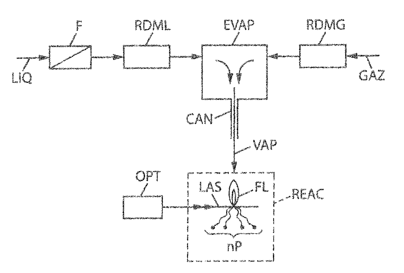
[0065]An exemplary embodiment of the invention is shown in FIG. 1.

[0066]The precursor, first in liquid form LIQ, is filtered by filter F. Its flow rate is then controlled by a mass flow controller RDML, which is followed by an evaporator EVAP, which then converts the precursor to the vapor phase VAP before interaction with the laser beam LAS.

[0067]Thus, it is proposed to couple a laser pyrolysis device with a mass flow controller RDML to control the precursor flow rate in liquid form LIQ, before converting it to the vapor phase VAP for injection into the pyrolysis reactor REAC.

[0068]The vapor VAP is entrained by a gas stream (preferably by an inert gas in the pyrolysis reaction, such as a rare gas, for example argon). This gas stream GAZ is also managed by a gas mass flow controller RDMG. The mixture of vapor and gas (referenced VAP) leaving the evaporator-mixer EVAP is finally conveyed to the laser pyrolysis reactor REAC via a line CAN of which the temperature is set so as to preve...


PUM

PropertyMeasurementUnit
temperatureaaaaaaaaaa
specific surface areaaaaaaaaaaa
frequencyaaaaaaaaaa

Abstract

The present invention relates to the synthesis of nanoparticles by laser hydrolysis. For this purpose, a precursor interacts with a laser beam (LAS) in a pyrolysis reactor (REAC) for producing nanoparticles (nP), characterized in that the precursor is firstly in the liquid state and is then converted into the vapour phase and in that the flow rate of the precursor is controlled in the liquid phase.

Description

TECHNICAL FIELD[0001]The present invention relates to the production of nanoparticles by laser pyrolysis.[0002]Nanostructured materials have undergone very strong development in the last ten years. This development is associated with the properties of these materials, which have opened up new fields of application in areas as varied as optics and catalysis.[0003]The grain size of the nanostructured materials may extend from a few nanometers to a few tens of nanometers, and may be selected according to the desired property for a given application. For example, thermomechanical ceramics have demonstrated plasticity at high temperature, while these materials normally have mechanically brittle behavior. This property is associated with a grain sliding effect and is observed in particular when the nanostructuring occurs at a scale of a few tens of nanometers. On the other hand, effects due to quantum confinement are observed for particles having a size of a few nanometers.[0004]To obtain...

Claims


Application Information

Patent Timeline
Patent Type & Authority Applications(United States)
IPC IPC(8): C01G1/04B01J19/08C01G1/02
CPCB82Y30/00C01G23/047C01G23/07C01P2002/82C01P2004/04C01P2004/51C01P2004/64C01P2006/12Y10S977/773
Inventor PORTERAT, DOMINIQUE
Owner COMMISSARIAT A LENERGIE ATOMIQUE ET AUX ENERGIES ALTERNATIVES
Why Eureka
Try Eureka