
Roll-To-Roll Plasma Enhanced Chemical Vapor Deposition Method of Barrier Layers Comprising Silicon And Carbon

a technology of chemical vapor deposition and plasma, which is applied in the direction of water-setting substance layered products, synthetic resin layered products, transportation and packaging, etc., can solve the problems of increasing the overall processing time required, reducing the production volume of the system, and not being able to continuously process by batch, etc., and achieves a high level of protection

Inactive Publication Date: 2010-04-15
DOW CORNING CORP
View PDF24 Cites 29 Cited by
  • Summary
  • Abstract
  • Description
  • Claims
  • Application Information

AI Technical Summary

Benefits of technology

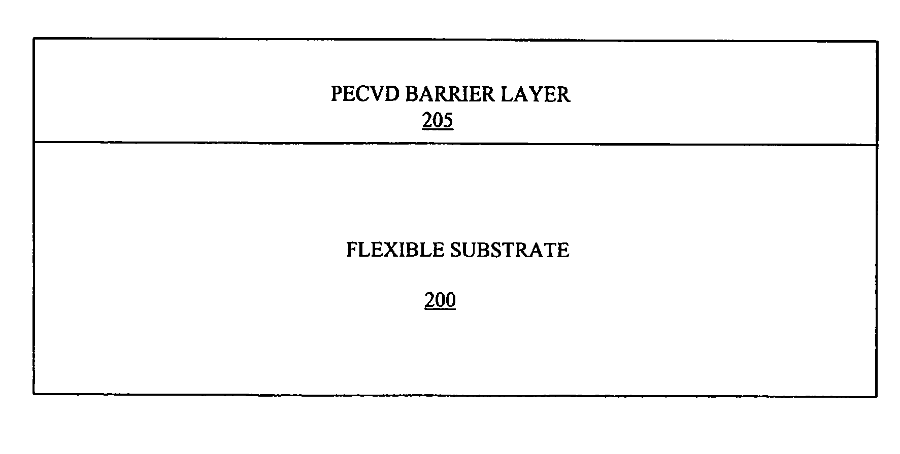
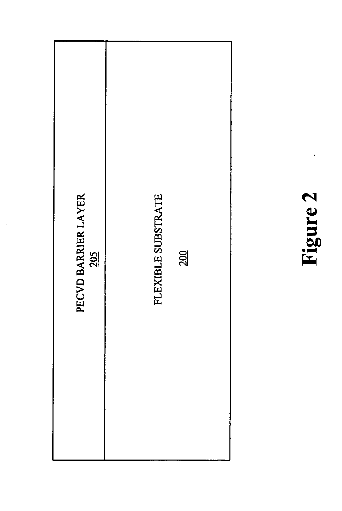
[0016]In another embodiment, a method is provided for a continuous vacuum method of processing-flexible web or film substrate. The method includes depositing a thin film silicon carbide alloy layer on a flexible web by exposing the flexible web to Penning discharge plasma deposition process. In one embodiment, the thin film silicon carbide alloy layer forms part of a barrier layer that provides high level of protection against water vapor (transmission less than 5.10−2 g / m2 / day at 38° C.) and against oxygen transmission (less than 5.10−2 cc / m2 / day at 38° C.) for a variety of polymer materials.
[0018]In yet another embodiment of the present invention, a barrier layer is formed on a flexible web or film substrate by a process. The process includes depositing a thin film silicon carbide alloy layer on a flexible web by exposing the flexible web to Penning discharge plasma deposition process. In one embodiment, the barrier layer provides a high level of protection against water vapor (transmission less than 5.10−2 g / m2 / day at 38° C.) and against oxygen transmission (less than 5.10−2 cc / m2 / day at 38° C.) for a variety of polymer materials.

Problems solved by technology

However, batch processing is not a continuous technique and typically requires loading the substrate into a process chamber, forming the barrier layer over the substrate, and then removing the substrate with the barrier layer formed thereon from the process chamber.
The time required to insert and / or remove the substrates from the chambers may increase the overall processing time required to form a barrier layer and reduce the production volume of the system.

Method used


Image

  • Roll-To-Roll Plasma Enhanced Chemical Vapor Deposition Method of Barrier Layers Comprising Silicon And Carbon
  • Roll-To-Roll Plasma Enhanced Chemical Vapor Deposition Method of Barrier Layers Comprising Silicon And Carbon
  • Roll-To-Roll Plasma Enhanced Chemical Vapor Deposition Method of Barrier Layers Comprising Silicon And Carbon

Examples


examples

[0047]The following examples are presented to better illustrate the coated substrates and methods of the present invention. However, these examples are intended to be illustrative and not to limit the present invention. In the examples, barrier coating deposition has been performed utilizing a single- and / or dual-asymmetric Penning discharge plasma source that operates in the medium frequency range. The temperature of the rollers in the deposition chamber has been maintained at 18-25° C. Tables 1 presents some of the physical properties of the barrier layers formed according to the present examples and FIGS. 4, 5 and 6 present some of the optical properties of the barrier layers.

examples 1

[0048]Barrier coating deposition has been performed at a plasma power range of 300-500 W (Table 1). The deposition process has been conducted introducing a silicon-carbon containing precursor, namely trimethylsilane ((CH3)3SiH), in the deposition chamber or a reactive gas mixture comprising trimethylsilane ((CH3)3SiH), and argon (Ar) with gas flow rate ratios of Ar / ((CH3)3SiH) up to 2.5 at a pressure range of 20-30 mTorr (Table 1). Barrier coatings have been deposited on polyethylenterephtalate (PET) film material. The thickness of the deposited barrier layers is typically around 0.75 μm. Barrier coatings contain silicon (Si), carbon (C), oxygen (O) as contaminant and hydrogen (H) in compositional ratios of Si / C=0.60-0.65 and O / Si=0.075-0.10, i.e. the material can be classified as hydrogenated silicon carbide based on the structural unit SiC:H (Table 1, FIG. 3—solid line). Barrier layer has a low water vapor transmission rate (WVTR), in the range of 10−3-10−2 g·m−2d−1, as it has bee...

examples 2

[0049]Barrier coating deposition has been performed at the power range of 250-300 W (Table 1). The deposition process has been conducted introducing a reactive gas mixture in the deposition system comprising silicon-carbon containing precursor, namely trimethylsilane ((CH3)3SiH), argon (Ar) and oxygen (O2) with gas flow ratios of Ar / ((CH3)3SiH)=1.0-1.5 and O2 / ((CH3)3SiH)=0.5-1.25 at a pressure range of 30-50 mTorr (Table 1). In this example, the barrier layer has been deposited on both PET and PEN flexible substrates. The thickness of the deposited barrier is typically in the range of 1.5-2.0 μm. Barrier coating contains silicon (Si), carbon (C), oxygen (O) and hydrogen (H) in compositional ratios of Si / C=0.95-1.10 and O / Si=0.35-1.0, i.e. the material can be classified as hydrogenated silicon oxycarbide based on the structural unit SiOC:H (Table 1, FIG. 3 dash and dotted lines). Barrier layers have low water vapor transmission rate (WVTR), in the range of 10−3 g·m−2d−1, as it has be...


PUM

PropertyMeasurementUnit
temperatureaaaaaaaaaa
dielectric constantaaaaaaaaaa
light transmittanceaaaaaaaaaa

Abstract

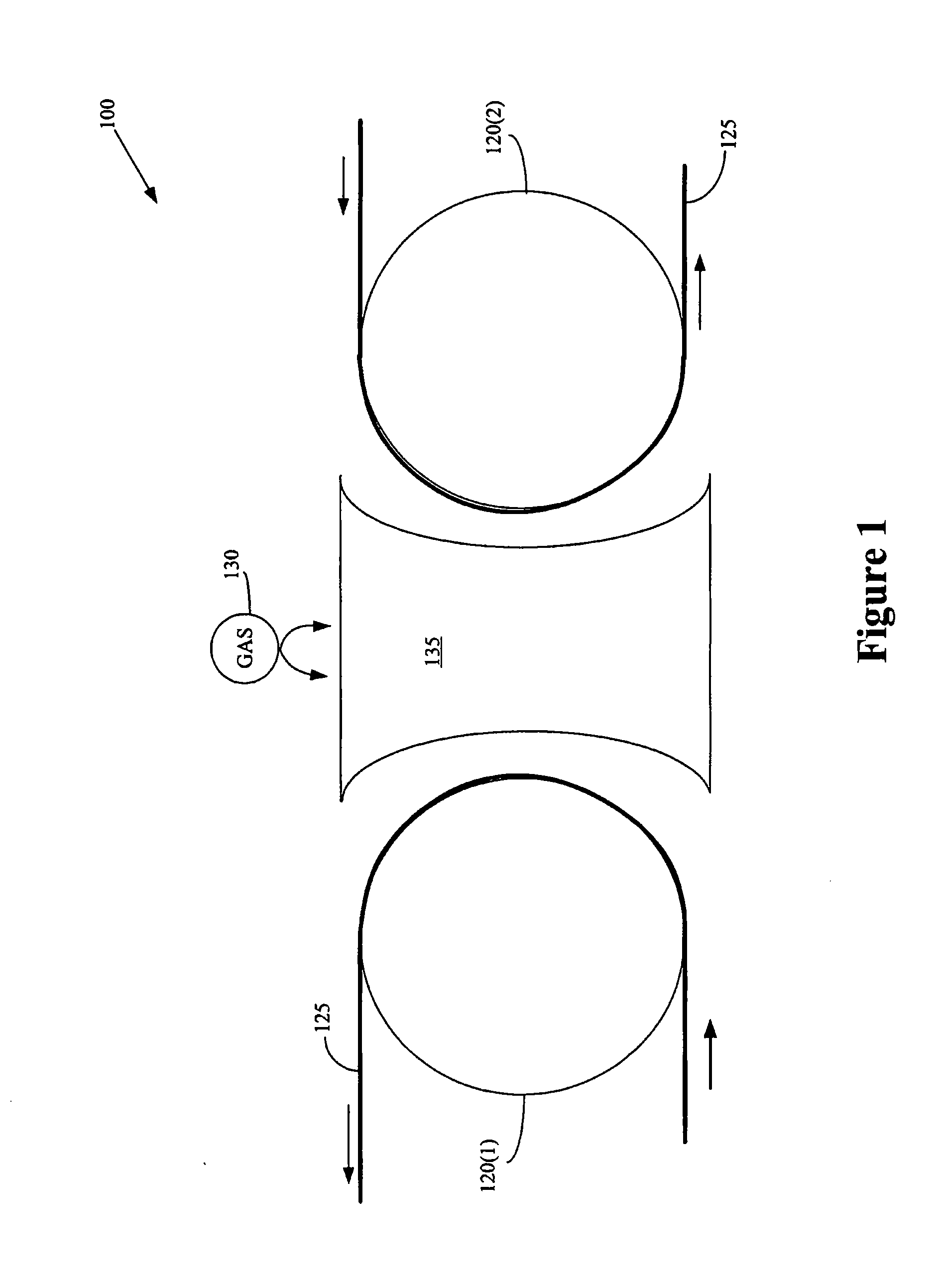
A method and process for forming a barrier layer on a flexible substrate are provided. A continuous roll-to-roll method includes providing a substrate to a processing chamber using at least one roller configured to guide the substrate through the processing chamber. The process includes depositing a barrier layer adjacent the substrate by exposing at least one portion of the substrate that is within the processing chamber to plasma comprising a silicon-and-carbon containing precursor gas. Also provided is a coated flexible substrate comprising a barrier layer based on the structural unit SiC:H, or SiOC:H, or SiOCN:H. The barrier layer possesses high density and low porosity. The barrier layer exhibits low water vapor transmission rate (WVTR) in the range of 10−2-10−4 g·m−2d−1 and is appropriate for very low permeability applications.

Description

CROSS REFERENCE TO RELATED APPLICATIONS[0001]This application is a continuation-in-part of co-pending PCT International Application No. PCT / US2008 / 055436, filed Feb. 29, 2008, which designated the United States, now published as WO 2008 / 121478, published Oct. 9, 2008, which application is based on U.S. Provisional Application Ser. No. 60 / 908,498, filed Mar. 28, 2007. The entire contents of the aforesaid applications are incorporated by reference herein.BACKGROUND OF THE INVENTION[0002]1. Field of the Invention[0003]This invention relates generally to deposition of barrier layers, and, more particularly, to roll-to-roll plasma enhanced chemical vapor deposition of a barrier layer comprising silicon and carbon.[0004]2. Description of the Related Art[0005]Barrier layers are commonly used to provide protection from a wide variety of potentially damaging conditions in the environment. For example, hydrophobic barrier layers may be used to provide protection from water, opaque barrier lay...

Claims


Application Information

Patent Timeline
Patent Type & Authority Applications(United States)
IPC IPC(8): B32B27/06C23C16/32B32B9/04B32B27/36B32B27/30B32B15/04
CPCC23C16/30C23C16/545C23C16/325Y10T428/31663Y10T428/249978Y10T428/31507Y10T428/3154C23C16/56B82Y30/00
Inventor ZAMBOV, LUDMIL M.SHAMAMIAN, VASGEN A.WEIDNER, WILLIAM K.LOBODA, MARK J.SNOW, STEVE A.CERNY, GLENN A.
Owner DOW CORNING CORP
Features
  • Generate Ideas
  • Intellectual Property
  • Life Sciences
  • Materials
  • Tech Scout
  • Unparalleled Data Quality
  • Higher Quality Content
  • 60% Fewer Hallucinations
Learn More