Boron film interface engineering

a technology of boron film and interface, applied in the direction of coating, chemical vapor deposition coating, plasma technique, etc., can solve the problems of increasing undesirable electrical interactions between adjacent circuit elements, reducing the width of these trenches, and increasing the aspect ratio of the trenches

Active Publication Date: 2010-04-22
APPLIED MATERIALS INC
View PDF30 Cites 103 Cited by
  • Summary
  • Abstract
  • Description
  • Claims
  • Application Information

AI Technical Summary

Benefits of technology

[0008]In one embodiment, the present disclosure provides a method of depositing a bilayer liner in a trench on a substrate in a processing chamber. The method includes forming an initiation layer having a thickness less than or about 15 Å and containing nitrogen and / or carbon. The method also includes forming a boron-containing layer on the initiation layer. The initiation layer reduces diffusion of boron from the boron-containing layer into the substrate.

Problems solved by technology

The increased density can increase undesirable electrical interactions between adjacent circuit elements and conducting lines.
As circuit densities increase, however, the widths of these trenches decrease, increasing their aspect ratios and making it progressively more difficult to fill the trenches without leaving voids.
A trench which is not completely filled is undesirable since the degree of isolation may be compromised which limiting the maximum operational frequency or otherwise adversely affect operation of the integrated circuit.
Especially for front-end processes, the presence of boron in a deposited film introduces a risk of migration of boron into the substrate.
The addition of boron may change a lightly doped region to a more heavily doped region and negatively affect the performance of a device.

Method used


Image

  • Boron film interface engineering
  • Boron film interface engineering
  • Boron film interface engineering

Examples


Embodiment Construction

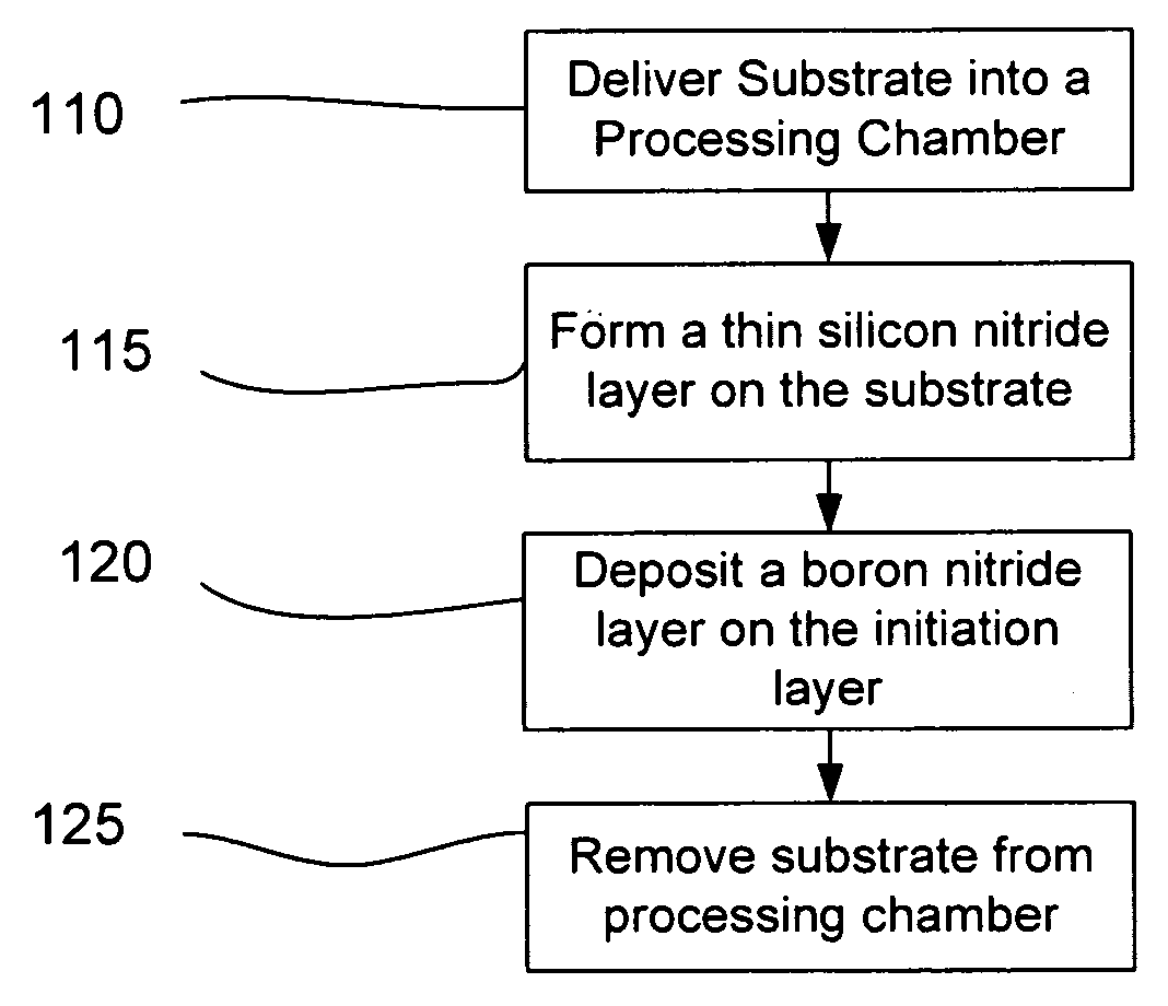
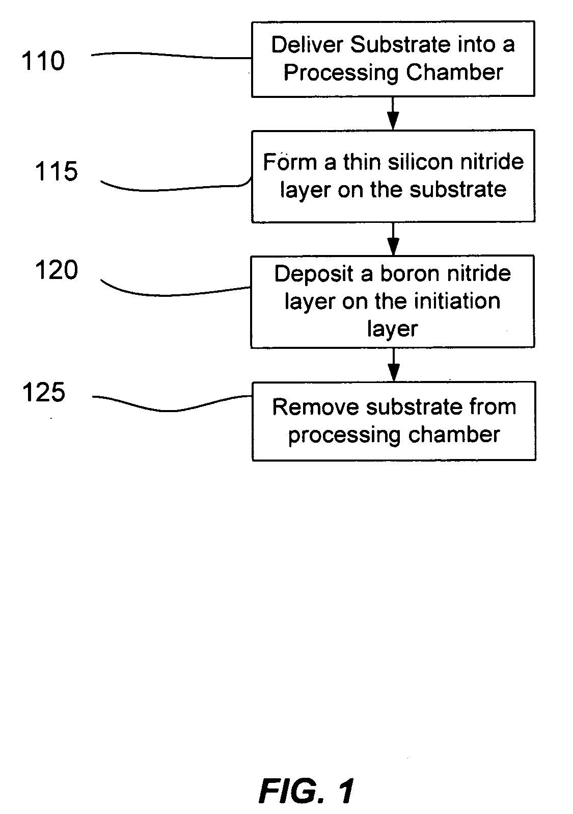
[0018]Aspects of the disclosure pertain to methods of depositing boron-containing liner layers on unpatterned or patterned substrates. The boron-containing liner layer provides benefits pertaining to the performance of a device, the longevity of a device or the manufacturing process flow. In embodiments, the boron-containing liner layer is a bilayer including an initiation layer of barrier material to inhibit the diffusion of boron from the bilayer into the underlying substrate. For some substrates, the initiation layer may also inhibit the diffusion of material from the substrate into or across the bilayer.

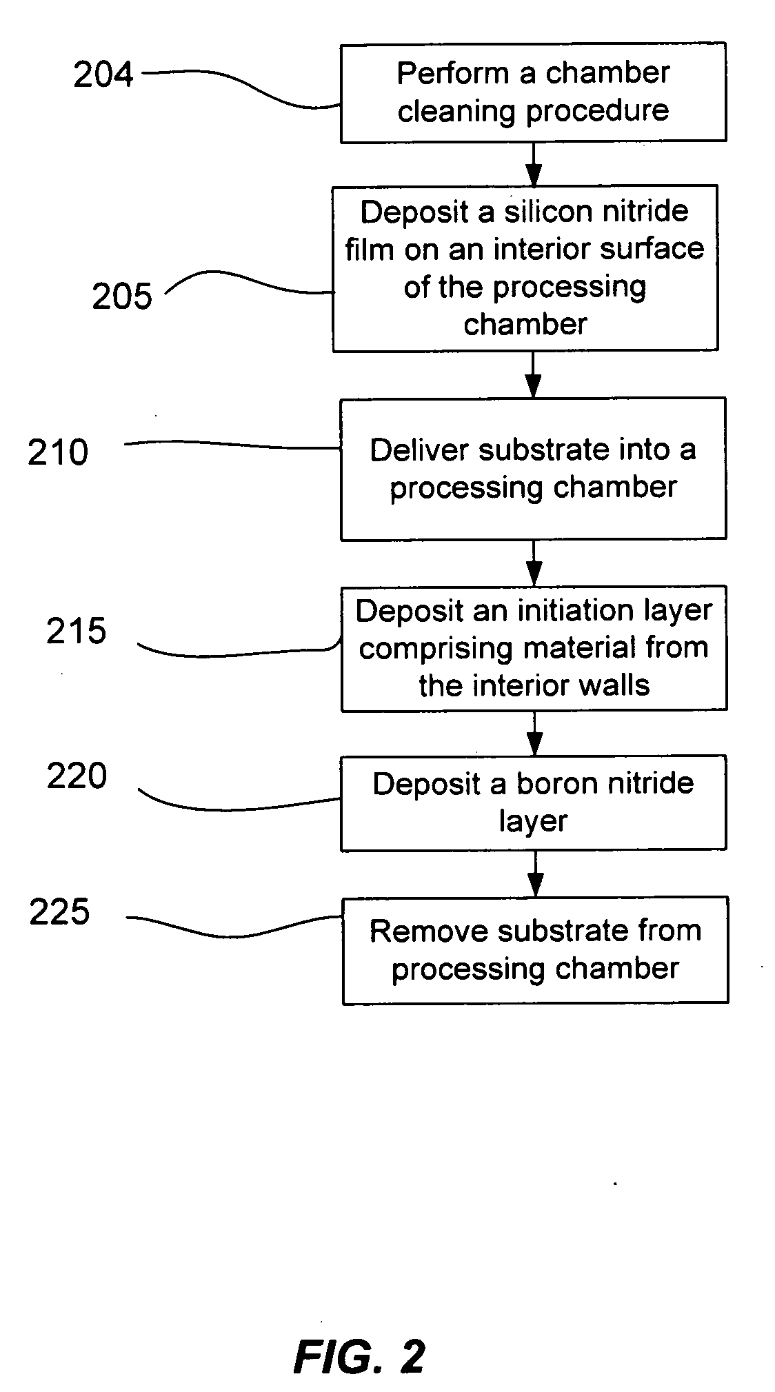
[0019]The initiation layer may be formed directly on the substrate. Alternatively, the initiation layer may be formed by depositing barrier material on the inner surfaces of the processing chamber in the absence of a substrate. This process may be referred to as seasoning the chamber herein. The barrier material may be redeposited with a plasma process after the substrate is intr...


PUM

PropertyMeasurementUnit
temperatureaaaaaaaaaa

Abstract

Methods of depositing boron-containing liner layers on substrates involve the formation of a bilayer including an initiation layer which includes barrier material to inhibit the diffusion of boron from the bilayer into the underlying substrate.

Description

CROSS-REFERENCES TO RELATED APPLICATIONS[0001]This application is related to U.S. patent application Ser. No. 11 / 765,257 and U.S. Prov. Pat. App. Ser. No. 61 / 042,638, both titled “BORON NITRIDE AND BORON NITRIDE-DERIVED MATERIALS DEPOSITION METHOD.” This application is also related to U.S. Prov. Pat. App. Ser. No. 61 / 106,076 titled “GAPFILL IMPROVEMENT WITH HIGH LOW ETCH RATE DIELECTRIC LINERS.”FIELD[0002]This application relates to manufacturing technology solutions involving equipment, processes, and materials used in the deposition, patterning, and treatment of thin-films and coatings, with representative examples including (but not limited to) applications involving: semiconductor and dielectric materials and devices, silicon-based wafers and flat panel displays (such as TFTs).BACKGROUND OF THE INVENTION[0003]Increasing the density of integrated circuits can increase speed and enable new applications. The increased density can increase undesirable electrical interactions between...

Claims


Application Information

Patent Timeline
Patent Type & Authority Applications(United States)
IPC IPC(8): C23C16/513B05D5/12C23C16/26C23C16/34
CPCC23C16/0272C23C16/342H01L21/76237H01L21/76224C23C16/4404
Inventor BALSEANU, MIHAELAXIA, LI-QUNWITTY, DEREK R.CHEN, YI
Owner APPLIED MATERIALS INC
Why Eureka
Try Eureka