
Radiation shielding members including nano-particles as a radiation shielding material and method for preparing the same

a radiation shielding material and radiation shielding technology, applied in the direction of conductive materials, nuclear engineering, nuclear elements, etc., can solve the problems of undesirable increase in the weight the surrounding environment with radioactivity, so as to increase the collision probability of the radiation shielding material, increase the radiation shielding effect, and reduce the thickness and volume of the shielding member.

Active Publication Date: 2010-04-29
GIPS CO LTD
View PDF9 Cites 31 Cited by
  • Summary
  • Abstract
  • Description
  • Claims
  • Application Information

AI Technical Summary

Benefits of technology

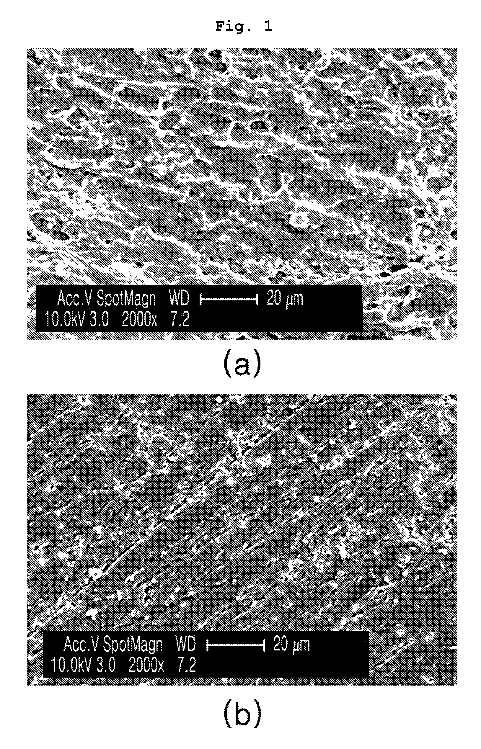
[0014]Leading to the present invention, thorough research carried out by the present inventors aiming to solve the problems encountered in the related art, resulted in the finding that nano-particles may be introduced as a radiation shielding material, thus increasing the collision probability of the radiation shielding material in the form of nano-particles with incident radiation in the shielding member, thereby increasing radiation shielding effects, and as well, the thickness and volume of the shielding member may be decreased compared to shielding members including particles having a size on at least the micro-scale as a shielding material, such that the weight of the shielding member may be reduced and the porosity of the shielding member may be minimized, thereby preventing the shielding effects and the properties of the shielding member from deteriorating due to the presence of pores and enabling the radiation shielding member to be usefully employed as a neutron absorber in spent fuel managing transport / storage environments and the like.

Problems solved by technology

In the case where the metallic material is used, problems in which the weight of the shielding member is undesirably increased owing to the high density of the metallic material incur.
Moreover, thermal neutrons make the surrounding material radioactive to thus pollute the surrounding environment with radioactivity.
However, the above patent does not recognize the fact that the particle size of the radiation shielding material has a great influence on radiation shielding performance.
Further, there is no report related to the preparation of a radiation shielding member using homogeneous dispersion of a radiation shielding material in the form of nano-particles in a polymer matrix.

Method used


Image

  • Radiation shielding members including nano-particles as a radiation shielding material and method for preparing the same
  • Radiation shielding members including nano-particles as a radiation shielding material and method for preparing the same
  • Radiation shielding members including nano-particles as a radiation shielding material and method for preparing the same

Examples


example 1

Preparation of Neutron Shielding Member 1

[0054]Step 1. Preparation of Neutron Absorbing Nano-Particles

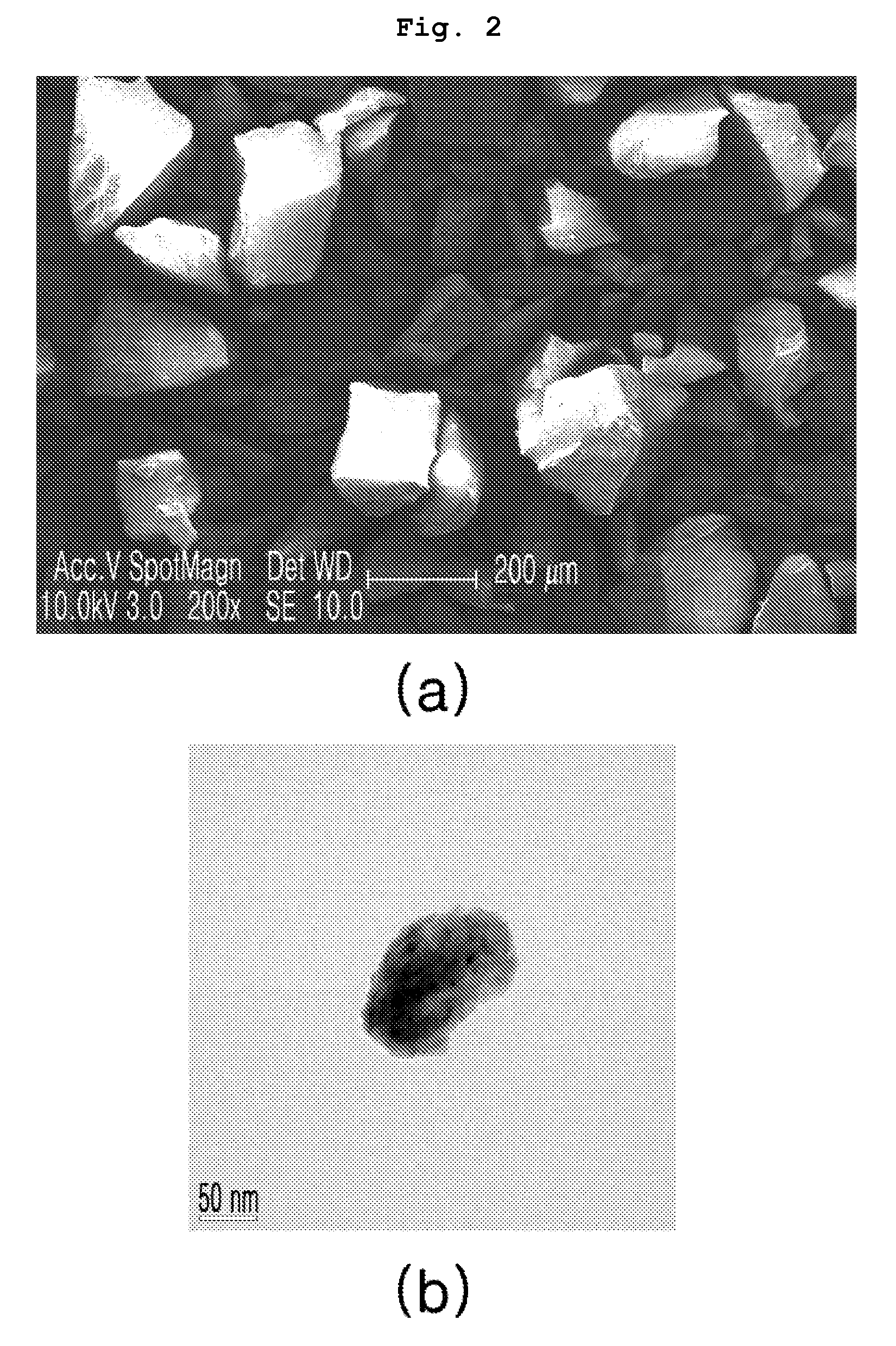
[0055]Commercially available boron oxide (B2O3, High Purity Chemicals, Japan) having a particle size of 200˜300 μm was subjected to ball milling at 1000 rpm for about 10 min, thus preparing boron compound nano-particles having a particle size of 100˜1000 nm.

[0056]Step 2. Surface Activation of Boron Compound Nano-Particles

[0057]The boron compound nano-particles obtained in step 1 were subjected to milling at 700 rpm for 60 min with the same amount of PVA, thus reducing the particle size and surface activating (coating) the boron compound nano-particles with PVA. The surface activation of the nano-particles can prevent the increase in the particle size as they collide each other. Thereby, the particle size could be advantageously maintained in the nano scale. In accordance therewith, the average particle size of the boron compound particles thus obtained was 210 nm.

[0058]Step 3. Dispe...

example 2

Preparation of Neutron Shielding Member 2

[0060]A neutron shielding member was prepared in the same manner as in Example 1, with the exception that the boron compound nano-particles surface-activated with an appropriate amount of PVA, used in step 3, had a boron content of 1.0 wt %.

example 3

Preparation of Neutron Shielding Member 3

[0061]Surface-activated B4C nano-powder (average particle size: about 50 nm) was prepared in the same manner as in steps 1 and 2 of Example 1, with the exception that B4C was used as the radiation shielding material. Thereafter, the nano-powder thus prepared was melt mixed with a HDPE polymer matrix with forcible stirring, and then injection molded, thus preparing a radiation shielding member. Thus, when using the present process, the nano-particles were confirmed to be homogeneously dispersed not only in the powder mixing but also in melt mixing.


PUM

PropertyMeasurementUnit
Nanoscale particle sizeaaaaaaaaaa
Percent by massaaaaaaaaaa

Abstract

Disclosed is a radiation shielding member having improved radiation absorption performance, including 80.0˜99.0 wt % of a polymer matrix or metal matrix and 1.0˜20.0 wt % of a radiation shielding material in the form of nano-particles having a size of 10˜900 nm as a result of pulverization, wherein the radiation shielding material is homogeneously dispersed in the matrix through powder mixing or melt mixing after treatment with a surfactant which is the same material as the matrix or which has high affinity for the matrix. A preparation method thereof is also provided. This radiation shielding member including the nano-particles as the shielding material further increases the collision probability of the shielding material with radiation, compared to conventional shielding members including micro-particles, thus reducing the mean free path of radiation in the shielding member, thereby exhibiting superior radiation shielding effects. At the same density, the shielding member has reduced thickness and volume and is thus lightweight. The porosity of the shielding member is minimized, thereby preventing the deterioration of shielding effects and properties of the shielding member and realizing applicability in spent fuel managing transport / storage environments and the like.

Description

CROSS-REFERENCE TO RELATED APPLICATION[0001]This patent application claims the benefit of Korean Patent Application Nos. 10-2008-0106438 filed Oct. 29, 2008, the contents of which are incorporated herein by reference. A claim of priority to all, to the extent appropriate is made.BACKGROUND OF THE INVENTION[0002]1. Field of the Invention[0003]The present invention relates to a radiation shielding members including nano-particles as a radiation shielding material and to a method for preparing the same.[0004]2. Description of the Related Art[0005]Radiation is largely classified into ionizing radiation and non-ionizing radiation, while radiation typically designates ionizing radiation in general.[0006]Ionizing radiation includes alpha rays, beta rays, protons, neutrons, gamma rays and X-rays, which cause ionization when passing through the matter, and is specifically divided into direct ionizing radiation and indirect ionizing radiation. Examples of direct ionizing radiation include alp...

Claims


Application Information

Patent Timeline
IPC IPC(8): G21F3/00G21F1/10
CPCG21F1/10G21F1/08G21F1/06B82Y40/00
Inventor KIM, JAEWOOUHM, YOUNG RANGLEE, BYUNGCHULJUNG, JINWOORHEE, CHANG KYULEE, MIN-KULEE, HEE MINLEE, SANG HOON
Owner GIPS CO LTD
Learn More