Process for removing gaseous contaminants from a feed gas stream comprising methane and gaseous contaminants

a technology of gaseous contaminants and feed gas stream, which is applied in the direction of gaseous fuels, separation processes, lighting and heating apparatus, etc., can solve the problems of energy efficiency of the separation process, and achieve the effect of improving the energy efficiency of the overall processing and the removal of gaseous contaminants

Inactive Publication Date: 2010-05-06
SHELL OIL CO
View PDF15 Cites 48 Cited by
  • Summary
  • Abstract
  • Description
  • Claims
  • Application Information

AI Technical Summary

Benefits of technology

[0007]It has now been found that in an integrated process for removing gaseous contaminants from gas streams that contain relatively large amount of gaseous contaminants the removal of gaseous contaminants can be improved, as well as the ener

Problems solved by technology

A disadvantage of this known method is that there is still room for improving the removal of the gaseous contaminants from the feed gas stream, ensuring that levels can be reached that are specified for pipeline transport of the feed gas stream or the production of liquefied natural gas.
Moreover, the

Method used


Image

  • Process for removing gaseous contaminants from a feed gas stream comprising methane and gaseous contaminants
  • Process for removing gaseous contaminants from a feed gas stream comprising methane and gaseous contaminants
  • Process for removing gaseous contaminants from a feed gas stream comprising methane and gaseous contaminants

Examples


Embodiment Construction

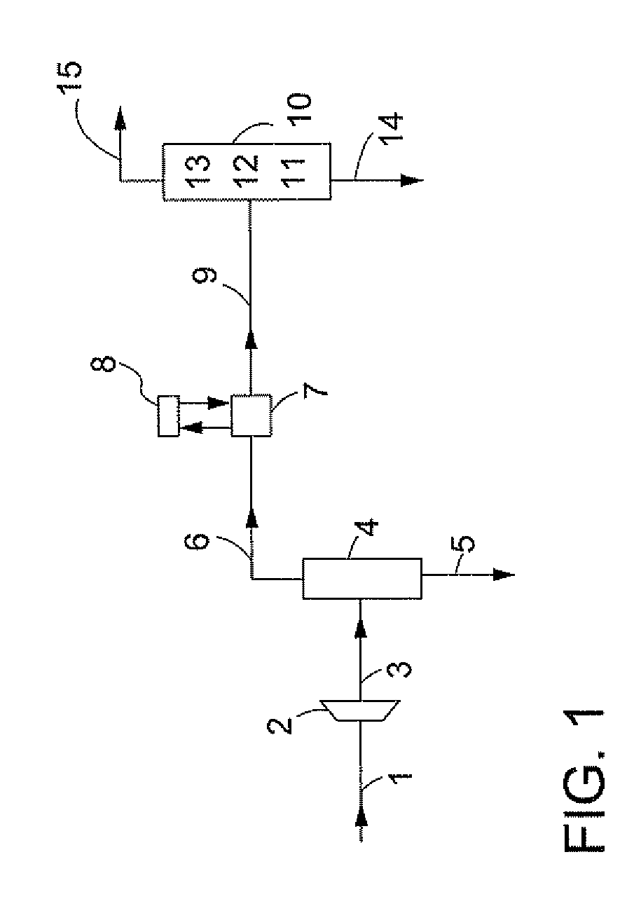
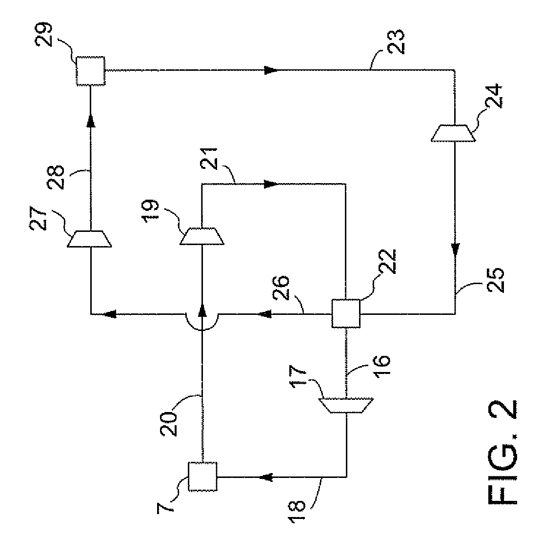
[0015]Referring initially to FIG. 1, natural gas via a conduit 1 is passed through an expansion means 2, whereby a stream is obtained comprising liquid phase contaminant and a methane enriched gaseous phase. The stream flows via a conduit 3 into a gas / liquid separator 4 wherein the two phases are separated from each other. The liquid phase contaminant is recovered via a conduit 5, whereas the methane enriched gaseous phase is passed via a conduit 6 into a heat exchanger 7. In heat exchanger 7 ethane is used as an external refrigerant whereby the ethane is cooled by means of an ethane / propane cascade 8 as depicted in more detail in FIG. 2. The cooling in heat exchanger 7 is such that liquid phase contaminant and a methane enriched gaseous phase are formed. The stream which comprises these two phases is then passed via a conduit 9 into a cryogenic separation vessel 10, which comprises a first distillation zone 11, a controlled freezing zone 12 and a second distillation zone 13. From t...


PUM

PropertyMeasurementUnit
Temperatureaaaaaaaaaa

Abstract

A process for removing gaseous contaminants from a feed gas stream that comprises a gaseous product and gaseous contaminants, comprising: providing the feed gas stream, cooling the feed gas stream to a temperature at which liquid phase contaminant is formed as well as a gaseous phase rich in gaseous product, separating the two phases by means of a gas/liquid separator, and introducing the gaseous phase rich in gaseous product into a cryogenic separation device that comprises a freezing zone and a distillation zone positioned below the freezing zone, and removing from the cryogenic separation device a bottom stream rich in liquid phase contaminant and lean in gaseous product, and a top stream rich in gaseous product and lean in gaseous contaminant. The invention further includes a device for carrying out the present process, the purified gas stream, and a process for liquefying a feed gas stream.

Description

RELATED CASES[0001]This case claims priority to European application 08168502.6, filed 6 Nov. 9, 2008, which is incorporated herein by reference.FIELD OF THE INVENTION[0002]The present invention relates to a process for the removal of gaseous contaminants from a feed gas stream which comprises a gaseous product and gaseous contaminants, in particular the removal of gaseous contaminants such as carbon dioxide and / or hydrogen sulphide from a natural gas or a gas stream from partial or complete oxidation processes, like syngas or flue gas.BACKGROUND OF THE INVENTION[0003]Gas streams produced from subsurface reservoirs such as natural gas, associated gas and coal bed methane or from (partial)oxidation processes, usually contain in addition to the gaseous product concerned such as methane, hydrogen and / or nitrogen contaminants such as carbon dioxide, hydrogen sulphide, carbon oxysulphide, mercaptans, sulphides and aromatic sulphur containing compounds in varying amounts. For most of the ...

Claims


Application Information

Patent Timeline
IPC IPC(8): F25J3/08
CPCB01D45/02B01D45/14B01D46/0031B01D50/002B01D53/002B01D2256/24B01D2257/304B01D2257/306B01D2257/308B01D2257/504B01D2258/06C10L3/10C10L3/102F25J3/0209F25J3/0233F25J3/0266F25J2200/02F25J2200/74F25J2205/04F25J2205/20F25J2215/04F25J2220/66F25J2240/02F25J2270/12F25J2270/60F25J2280/40Y02C10/12F25J2205/10Y02C20/40B01D50/20
Inventor ANDRIAN, DIKIVAART, RICK VAN DER
Owner SHELL OIL CO
Why Eureka
Try Eureka