Soft magnetic ribbon, magnetic core, magnetic part and process for producing soft magnetic ribbon

a soft magnetic ribbon and core technology, applied in the direction of magnetic bodies, cores/yokes, magnetic materials, etc., can solve the problems of low saturation magnetic flux density, difficult to process silicon steel sheets to thin sheets, large iron loss for high frequency applications, etc., and achieve high saturation magnetic flux density

Active Publication Date: 2010-05-06
HITACHI METALS LTD
View PDF4 Cites 31 Cited by
  • Summary
  • Abstract
  • Description
  • Claims
  • Application Information

AI Technical Summary

Benefits of technology

[0025]The present invention can provide a soft magnetic ribbon having high saturation magnetic flux density and low iron loss used for various transformers, laser power sources, pulse power magnetic parts for accelerators, various reactors for high current application, choking coils f

Problems solved by technology

The silicon steel sheet is made of an inexpensive material and has high magnetic flux density, but a problem of the silicon steel sheet is that its iron loss is large for high frequency applications.
Another problem is that it is very difficult to process the silicon steel sheet to a thin sheet like an amorphous ribbon owing to the production process thereof and it is disadvantageous due to a large loss caused by a large eddy current loss.
A problem of the ferrite material is its low saturation magnetic flux density and poor magnetic thermal properties.
Another problem is that the ferrite, which is easily magnetically saturated, is not suitable for high power applications in which the operation magnetic flux density is high.
Further, a problem of a Co-base

Method used


Image

  • Soft magnetic ribbon, magnetic core, magnetic part and process for producing soft magnetic ribbon
  • Soft magnetic ribbon, magnetic core, magnetic part and process for producing soft magnetic ribbon
  • Soft magnetic ribbon, magnetic core, magnetic part and process for producing soft magnetic ribbon

Examples


example 1

[0073]The ribbons, each having a width of 5 mm and a thickness of about 20 μm and each having the composition shown in Table 1 were prepared by a melt-quenching process using a single roll. The alloy ribbon was prepared by ejecting a molten alloy heated to 1300° C. onto a Cu—Be alloy roll having an outside size of 300 mm rotating at a peripheral speed of 32 m / s. As a result of an X-ray diffraction and transmission electron microscope (TEM) observation, it was found that the ribbon includes a structure dispersed in an amorphous phase in the volume fraction of less than 30%.

[0074]The ribbon was annealed so that the average rate of temperature rise at 300° C. or higher is about 200° C. / min or more. The ribbon was held at a holding temperature of 450° C. for 10 minutes, and then allowed to cool to obtain the soft magnetic ribbon of the present invention.

[0075]In each sample were present a crystal layer having a thickness of about 20 nm on the top surface of the ribbon, an amorphous laye...

example 2

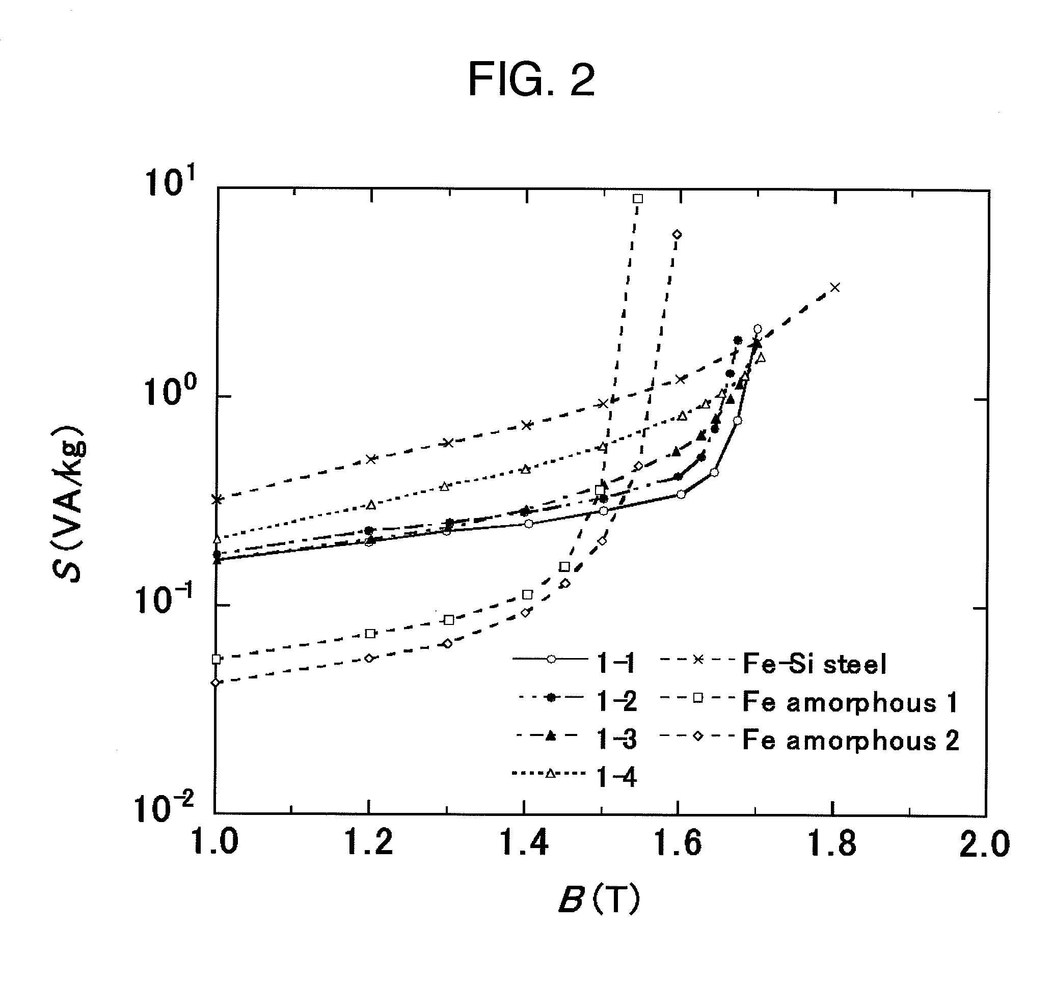
[0077]The soft magnetic ribbon produced in Example 1 was used to measure apparent power. FIG. 2 shows the relation between the apparent power and the magnetic flux density of the soft magnetic ribbon of the present invention. Further, Table 2 shows the data on apparent power S1.55 / 50, S1.60 / 50, and S1.65 / 50 measured at conditions of 50 Hz and 1.55 T, 1.60 T, and 1.65 T, respectively, for the alloy compositions of the soft magnetic ribbons of the present invention (Examples 1-1 to 1-4). The data of a grain-oriented silicon steel sheet is also shown for comparison.

[0078]The soft magnetic ribbon of the present invention has apparent power properties better than those of Fe-based amorphous materials and grain-oriented silicon steel sheets in a wide region of magnetic flux density of about 1.55 T to 1.7 T. These results in combination with the results in Example 1 show that the soft magnetic ribbon of the present invention has particularly excellent soft magnetic properties in the region...

example 3

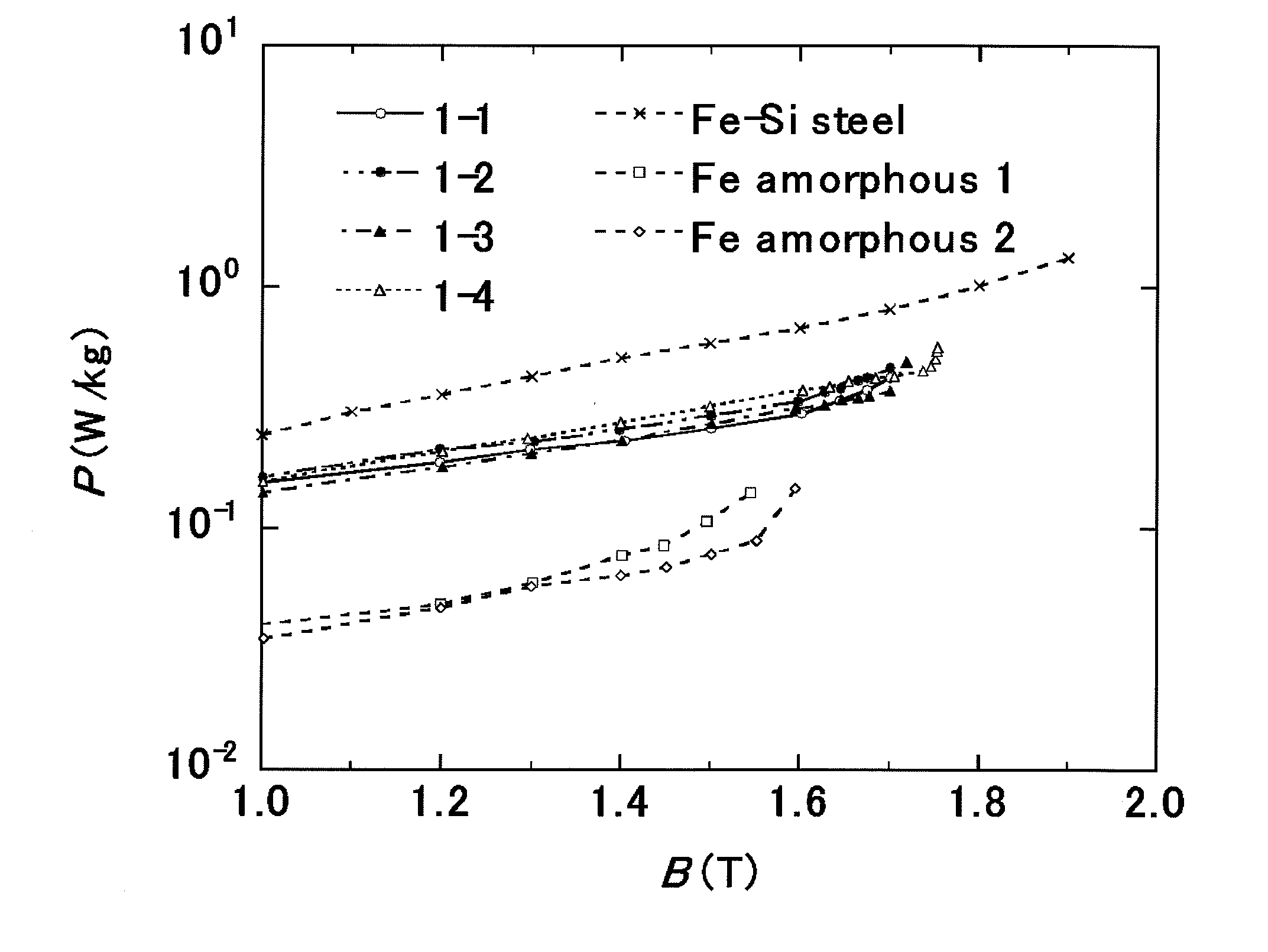
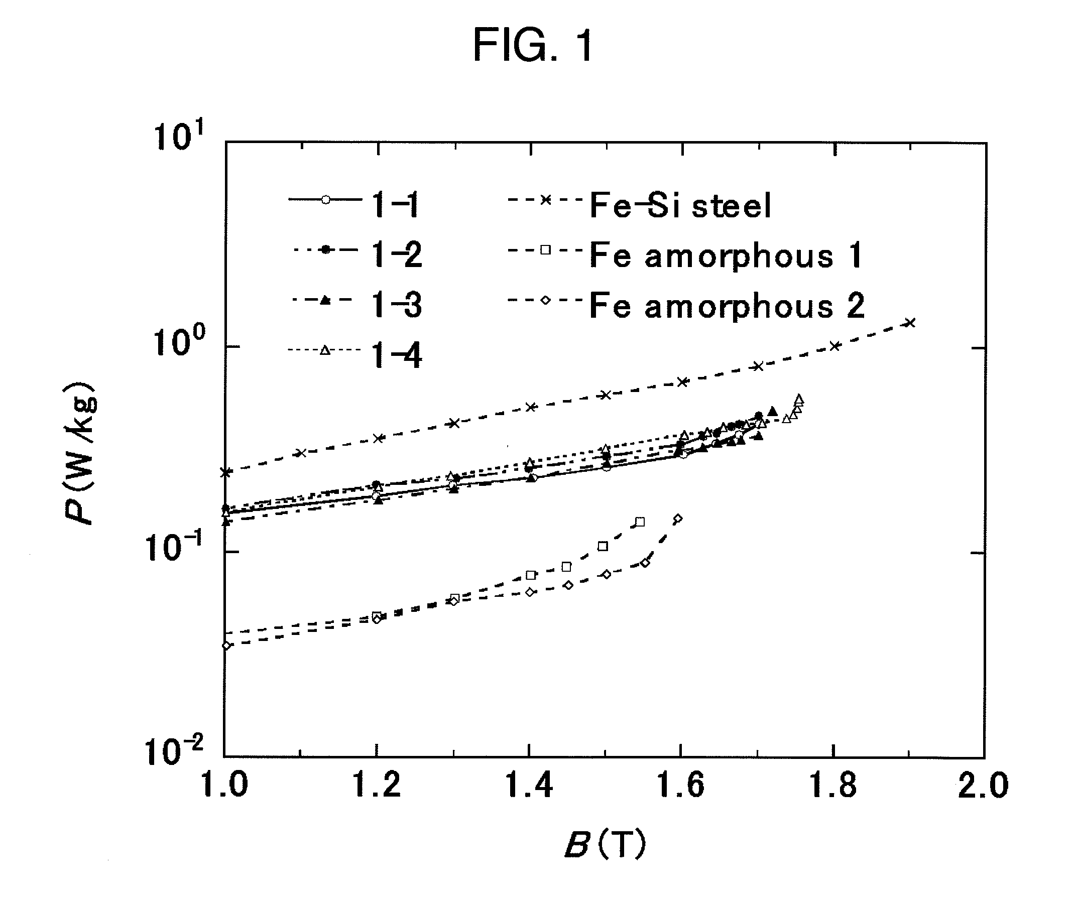
[0079]The soft magnetic ribbon produced in Example 1 was used to measure iron loss at a frequency of 400 Hz and 1 kHz. Table 3 shows the iron loss P1.0 / 400 and P0.5 / 1 k at 1.0 T and 400 Hz, and 0.5 T and 1 kHz, respectively, of the soft magnetic ribbons of the present invention and a grain-oriented silicon steel sheet. The difference of the iron loss between the inventive materials and the grain-oriented silicon steel sheet increases with increasing frequency, showing that the inventive materials are suitable for high frequency applications. Further, FIG. 3 shows the results of the magnetic flux density dependence of iron loss for each frequency, measured by using the soft magnetic ribbons in Examples 1 to 4.

TABLE 3Presence ofCompositionamorphousP1.0 / 400P0.5 / 1kName(Feature)layer(W / kg)(W / kg)Example 1-1Febal.Cu1.4Si5B13Yes2.63.6Example 1-2Febal.Cu1.4Si4B14Yes2.73.7Example 1-3Febal.Cu1.4Si3B12P2Yes1.91.6Example 1-4Febal.Cu1.35Si2B12P2Yes1.81.3Grain-OrientedFe—Si (230 μmt)No7.810.4silic...


PUM

PropertyMeasurementUnit
Grain sizeaaaaaaaaaa
Temperatureaaaaaaaaaa

Abstract

A soft magnetic ribbon that especially in a relatively low magnetic field region of 500 A/m or less, is high in the squareness of magnetic flux density-magnetization curve. There is disclosed a soft magnetic ribbon of 100 μm or less thickness comprising a parent phase structure in which by volume ratio, 30% or more of crystal grains of 60 nm or less (not including 0) crystal grain diameter are dispersed in an amorphous phase and comprising an amorphous layer disposed on the surface side of the parent phase structure. Preferably, the soft magnetic ribbon is represented by the composition formula Fe100-x-yCuxXy (wherein X is at least one element selected from among B, Si, S, C, P, Al, Ge, Ga and Be), in which the atomic percents (%) satisfy the relationships 0<x≦5 and 10≦y≦24.

Description

TECHNICAL FIELD[0001]The present invention relates to a soft magnetic ribbon having high saturation magnetic flux density and good squareness used for various transformers, laser power sources, pulse power magnetic parts for accelerators, various reactors, noise countermeasures, various motors, various generators, and the like, and to a magnetic core and a magnetic part using the ribbon and a process for producing the soft magnetic ribbon.BACKGROUND ART[0002]Silicon steels, ferrites, an amorphous alloys, a Fe-based nanocrystalline alloys, and the like are known as magnetic materials having high saturation magnetic flux density and excellent in alternating-current magnetic properties used for various transformers, reactors / choking coils, noise suppression parts, laser power sources, pulse power magnetic parts for accelerators, various motors, various generators, and the like.[0003]The silicon steel sheet is made of an inexpensive material and has high magnetic flux density, but a pro...

Claims


Application Information

Patent Timeline
IPC IPC(8): H01F1/153C22C38/00C22C45/02C21D6/00
CPCC21D8/1211C21D8/1272C21D2201/03C21D2201/05C22C33/003C22C38/002C22C38/02C22C38/12C22C38/16C22C45/02H01F1/15308H01F3/04H01F41/0226H01F1/15333C21D6/00H01F1/153
Inventor OHTA, MOTOKIYOSHIZAWA, YOSHIHITO
Owner HITACHI METALS LTD
Why Eureka
Try Eureka