
Fixing member, method for producing the same, and fixing device

a technology of fixing parts and fixing parts, which is applied in the direction of electrographic process equipment, instruments, optics, etc., can solve the problems of reducing the cohesive force of the overall toner, roller filming and/or a carrier-spent phenomenon, and high probability of exposure of wax, etc., and achieves high gloss and withou. , the effect of increasing the roughness of the image surfa

Active Publication Date: 2010-05-13
RICOH KK
View PDF9 Cites 12 Cited by
  • Summary
  • Abstract
  • Description
  • Claims
  • Application Information

AI Technical Summary

Benefits of technology

[0020]The present invention is aimed at solving the problems in related art and achieving the following object. An object of the present invention is to provide a fixing member which surely promotes separation of a recording medium from the fixing member even at high speed, which can reduce the incidence of image defects and paper jams and form a high-quality image, and which undergoes less temporal deformation; a method for producing a fixing member; and a fixing device using the fixing member, which is capable of realizing stable image fixation for a long period of time.
[0021]As a result of carrying out a series of earnest examinations in an attempt to solve the problems, the present inventors have found that by forming numerous through-holes (hereinafter, otherwise referred to as “depressions”) in a release layer of a fixing member which are different from other portions (protrusions) in terms of affinity for a release agent in toner and which can deform by pressure, it is possible to surely promote separation of a recording medium from the fixing member even at high speed, reduce the incidence of image defects and paper jams and form a high-quality image.
[0023]The fixing member according to <1> includes an elastic layer and a release layer, wherein the release layer has a plurality of through-holes formed between its front surface and its surface on the opposite side to the front surface, and part of the elastic layer in contact with the release layer fills the through-holes upon provision of pressure for fixing the unfixed image to the recording medium. When this fixing member is used in a fixing device of an image forming apparatus, it is possible to realize an image fixing and medium separating process in a stable manner without causing the winding of a recording medium and obtain a highly glossy, high-quality image without increasing the roughness of the image surface at the time of nipping with pressurization for image fixation.<2> The fixing member according to <1>, wherein the part of the elastic layer in contact with the release layer fills the through-holes upon the provision of the pressure for fixing the unfixed image to the recording medium, and the front surface of the release layer forms a smooth surface when the unfixed image is pressurized for its fixation.<3> The fixing member according to one of <1> and <2>, wherein the base material in the fixing member has a hollow structure in a cylindrical shape, and a heating medium is provided in the hollow structure.<4> The fixing member according to any one of <1> to <3>, wherein a material constituting the release layer contains a fluorine-based polymer.<5> The fixing member according to any one of <1> to <4>, wherein a material constituting the elastic layer is a rubber material.<6> The fixing member according to <5>, wherein the rubber material has a molecular arrangement whose main-chain component contains siloxane bonds.<7> The fixing member according to one of <5> and <6>, wherein the rubber material is fluorosilicone rubber.<8> The fixing member according to any one of <1> to <7>, wherein the universal hardness of the elastic layer is equal to or lower than the universal hardness of the release layer.
[0025]Since the fixing device according to <20> is provided with the fixing member of the present invention, the durability and reliability of the fixing device improve.<21> A fixing method including: placing the release layer of the fixing member according to any one of <1> to <15> in such a direction that the release layer touches an unfixed image formed with a developer, when the unfixed image is fixed to a recording medium.<22> An image forming apparatus including: a latent electrostatic image bearing member; a unit configured to form a latent electrostatic image on the latent electrostatic image bearing member; a developing unit configured to develop the latent electrostatic image using a toner so as to form a visible image; a transfer unit configured to transfer the visible image onto a recording medium; and a fixing unit configured to fix the transferred visible image to the recording medium, wherein the fixing unit is the fixing device according to <20>.
[0026]Since the image forming apparatus according to <22> includes the fixing unit (fixing device) of the present invention, it can be suitably utilized for electrophotographic copiers, facsimiles, laser beam printers, etc. with high durability and reliability, and can thus contribute to reduction in environmental loads and improvement in customer satisfaction.
[0027]According to the present invention, it is possible to solve the problems in related art and provide the following: a fixing member which surely promotes separation of a recording medium from the fixing member even at high speed, which can reduce the incidence of image defects and paper jams and form a high-quality image, and which undergoes less temporal deformation; a method for producing a fixing member; and a fixing device using the fixing member, which is capable of realizing stable image fixation for a long period of time.

Problems solved by technology

However, even when such a fixing member is used, the melting toner is liable to adhere to the surface of the fixing member owing to its softness and high viscosity, so that the winding of the recording medium such as paper may arise.
However, problems of serious side effects such as the following have been pointed out: when a large amount of wax is contained in the toner, the wax is highly likely to be exposed at the surface of the toner, which causes roller filming and / or a carrier-spent phenomenon; moreover, since a large amount of low-viscosity wax is mixed in the toner, offset arises owing to a reduction in the cohesive force of the overall toner.
Although the problems such as roller filming and a carrier-spent phenomenon can be lessened by making a polymerized toner, etc. have a multilayer structure, the problem of the reduction in cohesive force cannot be prevented.
Further, there is a problem of smearing; for example, application of a large amount of oil can make paper sticky.
This problem can be solved by reducing the amount of the oil applied; however, there is such a problem that when the amount is reduced in this manner, the oil is repelled by a release surface subjected to image fixation, the repelled oil is formed into the shape of dots and so cannot uniformly cover a fixation surface, and thus releasing effects are nullified.
However, if the separation claw is brought into contact with the fixing member in this manner, the contact portion of the separation claw may scratch the fixing member, so that scratches may be transferred in a fixing step and an abnormal image may be thereby formed.
Accordingly, ways of reducing the damaging behavior of the separation claw to the fixing member, for example by providing the separation claw with a fluorine-based resin surface layer superior in slidability or rounding angles in the vicinity of the contact portion of the separation claw, have been devised; however, when paper powder produced during printing is sandwiched between the separation claw and the fixing member, the paper powder is pressed against the fixing member by the separation claw, which too causes scratches, and thus an abnormal image may arise.
However, this fixing member is problematic in that a separation claw presses into the elastic layer further, thereby easily damaging the fixing member.
In other words, when the recording medium such as paper is electrostatically or chemically attached to the fixing member, there is a great reduction in separating function, and the separating performance tends to be insufficient especially at high linear velocity.
In the case where a copy pattern with a large amount of adhesive toner is used, initial separation does not take place in time, which causes an image portion to touch the separation plate, and thus an image defect such as formation of streaks arises.
Consequently, as the linear velocity increases, there is a paper jam caused on the separation plate.
Meanwhile, Japanese Patent (JP-B) No. 4015785 describes improvement in surface adhesion by forming fluorine resin protrusions on a fluorine rubber surface layer; however, serious temporal deformation arises owing to abrasions to the protrusions caused by the contact with recording media, dust, etc., and thus long-term stable effects cannot be obtained.
JP-A No. 2007-316529 describes provision of depressions capable of holding wax components as a release agent of toner; however, since the shape is obtained merely by processing the surface of a single member (having an equal hardness), a change cannot be produced in wettability, and thus the wax holding force is weak.
Also, in some cases, the fixed surface shape is transferred to an output image, thereby reducing the glossiness of the image and lowering the image quality.

Method used


Image

  • Fixing member, method for producing the same, and fixing device
  • Fixing member, method for producing the same, and fixing device
  • Fixing member, method for producing the same, and fixing device

Examples


example 1

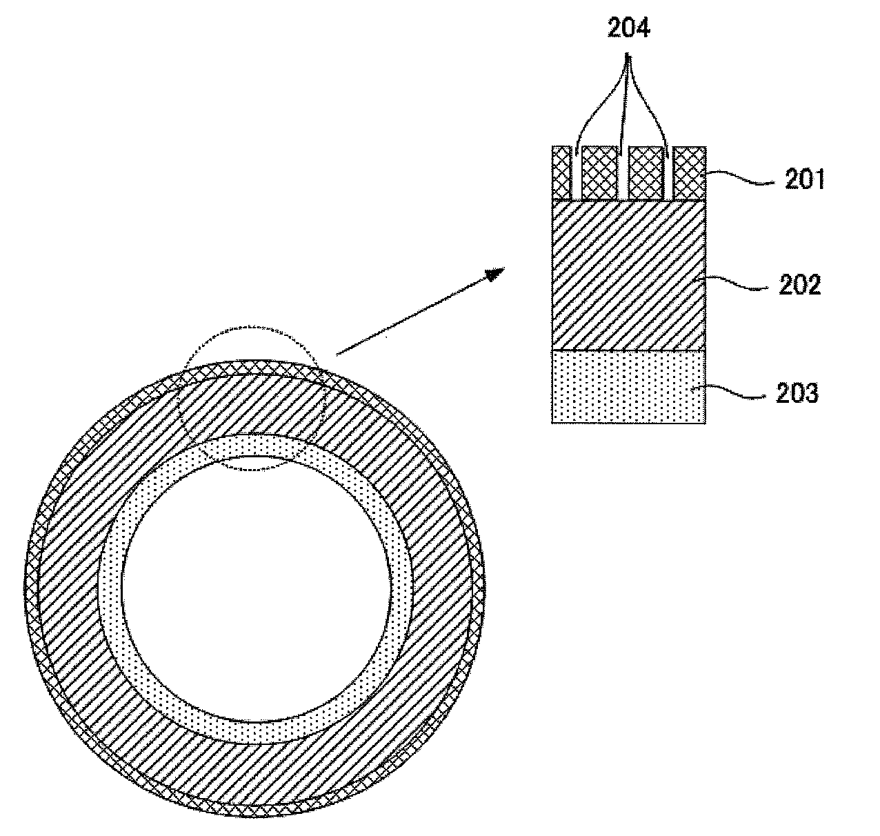
[0133]A silicone primer layer as an underlayer was formed and dried on a cylindrical base material (made of a polyimide resin) having a length of 320 mm, a diameter of 60 mm and a thickness of 50 μm, then fluorosilicone rubber (X36-420U, manufactured by Shin-Etsu Chemical Co., Ltd.) was applied onto the silicone primer layer by blade coating, which was followed by heating at 150° C. for 10 minutes, and an elastic layer having a thickness of 200 μm was thus formed.

[0134]Next, 10 g of PFA particles (powdered fluorine resin, MP102, manufactured by DU PONT-MITSUI FLUOROCHEMICALS COMPANY, LTD.) classified so as to have diameters of 0.1 μm to 50 μm (mainly 10 μm) were attached onto the elastic layer by powder coating.

[0135]Subsequently, a fluorine-based elastomer (SIFEL615C, manufactured by Shin-Etsu Chemical Co., Ltd.) was applied over the PFA particle layer, which was followed by heating at 150° C. for 60 minutes, and a release layer having a thickness of 5.0 μm was thus formed.

[0136]Ne...

example 2

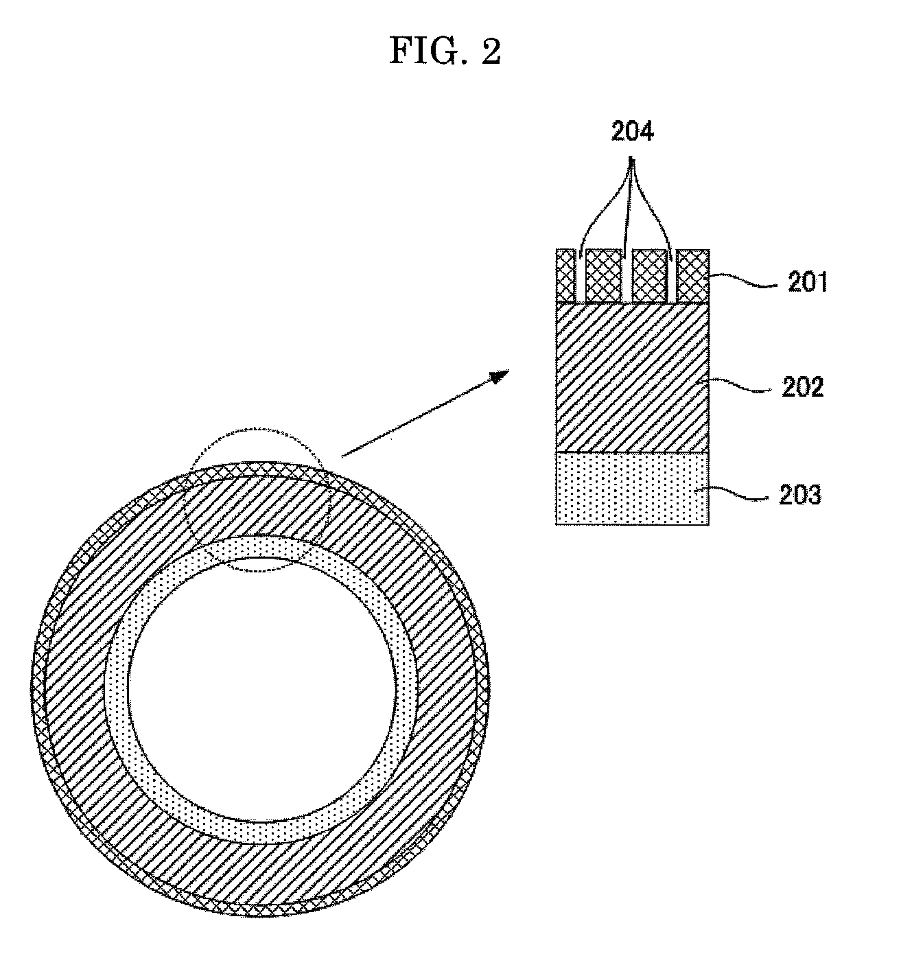
[0146]A fixing member of Example 2 was produced in the same manner as in Example 1, except that, instead of the fluorosilicone rubber in the elastic layer, silicone rubber (DY35-2083, manufactured by Dow Corning Toray Co., Ltd.) was applied by blade coating so as to have a thickness of 200 μm, which was followed by heating at 150° C. for 30 minutes and then secondary vulcanization at 200° C. for 4 hours.

[0147]Regarding the obtained fixing member of Example 2, the universal hardness of the release layer was 0.8 N / mm2 (when the indenter had been pushed to a depth of 5 μm), and the universal hardness of the elastic layer was 0.4 N / mm2 (when the indenter had been pushed to a depth of 5 μm).

[0148]Also regarding the obtained fixing member of Example 2, the receding contact angle of the surface of the release layer to purified water was 91°, and the receding contact angle of the surface of the elastic layer to purified water was 76°. When the quartz plate was brought into contact with the ...

example 3

[0149]A fixing member of Example 3 was produced in the same manner as in Example 1, except that, instead of the fluorine-based elastomer in the release layer, a fluorine-based carbon compound (OPTOOL HD, manufactured by DAIKIN INDUSTRIES, LTD, diluted solution (1.0% by mass)) was only applied by dipping and kept at a relative humidity of 90% and a temperature of 80° C. for 30 minutes, which was followed by drying at 150° C. for 10 minutes, and a release layer having a thickness of 0.02 μm was thus formed.

[0150]Regarding the obtained fixing member of Example 3, the universal hardness of the release layer was 0.2 N / mm2 (when the indenter had been pushed to a depth of 5 μm), and the universal hardness of the elastic layer was 0.2 N / mm2 (when the indenter had been pushed to a depth of 5 μm).

[0151]Also regarding the obtained fixing member of Example 3, the receding contact angle of the surface of the release layer to purified water was 90°, and the receding contact angle of the surface o...


PUM


Abstract

To provide a fixing member for fixing to a recording medium an unfixed image formed with a developer, the fixing member including: a base material; an elastic layer which is provided outside the base material and has an elastic deformation property; and a release layer which is provided outside the elastic layer and promotes separation of the recording medium from the fixing member, wherein the release layer has a plurality of through-holes formed between its front surface and its surface on the opposite side to the front surface, and part of the elastic layer in contact with the release layer can fill the through-holes upon provision of pressure for fixing the unfixed image to the recording medium.

Description

BACKGROUND OF THE INVENTION[0001]1. Field of the Invention[0002]The present invention relates to a fixing member, a method for producing a fixing member, and a fixing device using the fixing member.[0003]2. Description of the Related Art[0004]Conventionally, electrophotographic image forming apparatuses, e.g. copiers, printers and facsimiles, generally include photoconductor drums which rotate, and a photosensitive layer of each photoconductor drum is uniformly charged and then exposed to a laser beam coming from a laser scanning unit so as to form a latent electrostatic image thereon. The latent electrostatic image is developed with toner and then transferred onto transfer paper that is a recording medium. Subsequently, the transfer paper is passed through a thermal fixation device where the developed image is thermally fixed on the transfer paper (thermal fixing method).[0005]In full-color copiers and laser printers, toners of four colors, i.e. magenta (M), cyan (C), yellow (Y) an...

Claims


Application Information

Patent Timeline
Patent Type & Authority Applications(United States)
IPC IPC(8): G03G15/20G03G5/00
CPCG03G15/2053
Inventor KONDOH, TSUNEAKINATORI, JUNICHIROSUGAWARA, TOMOAKI
Owner RICOH KK
Features
  • Generate Ideas
  • Intellectual Property
  • Life Sciences
  • Materials
  • Tech Scout
  • Unparalleled Data Quality
  • Higher Quality Content
  • 60% Fewer Hallucinations
Learn More