Recoil reducer for use with a firearm

a technology of reducer and firearm, which is applied in the field of firearms, can solve the problems of reducing the accuracy of the user's shot, pain to the user's shoulder, and the significant recoil experienced by the user in the shoulder-borne weapon, so as to increase the resistance of the device, and reduce the number of variables

Active Publication Date: 2010-05-20
SIMMS NATHAN
View PDF29 Cites 30 Cited by
  • Summary
  • Abstract
  • Description
  • Claims
  • Application Information

AI Technical Summary

Benefits of technology

[0029]As a corollary, the position of the magnet and magnet mover also helps to maintain the recoil reducer in its rest position, when that is so desired, and the magnet and magnet mover help to add additional resistance to movement of the device away from its rest position. This feature has several advantages. One advantage is that it makes the gun “more steady,” and thereby aids the user in aiming the gun, and helps the user to be more accurate with his shooting.
[0030]One important use of the present invention is in hunting and in target shooting. In target shooting applications, the accuracy of the user's shot is paramount, as the primary purpose of a target shooting exercise is to determine the most accurate shooter among the contestants. When aiming at a target, the user of the gun helps to reduce the number of variables that can contribute to the inaccuracy of the shot. To that end, users will often time their shot with their breathing and heart beat, so that their breathing and heart beat cycle is at a point where it is less likely to cause the gun to shake, and thereby cause their aim to be off.
[0031]Another place where variation can be introduced in a gun with a recoil reducer, is the relative movement of the first and second stock members. In a traditional, “one piece” stock containing gun, this issue is largely irrelevant, because a one piece stock does not have multiple pieces that can move with respect to each other. However, as a stock containing recoil reducer includes a multi-piece stock, the possibility exists that the pieces of the multi-piece stock could move with respect to each other, to thereby induce a movement that may impact the shooter's accuracy. To address this problem, the Applicants' magnet helps to add additional resistance to the movement of either the recoil reducer mechanism, or to the stock members, when the stock member and recoil reducer mechanisms are at its rest position.
[0032]One feature of the present invention is that the coupling between the recoil reduction mechanism and the first stock member; the shock absorber plunger of the recoil reduction mechanism; and the coupling member between the second stock member and the recoil reduction mechanism are all disposed on a co-linear axis. This co-linear disposition helps to direct the recoil force along a single line. This single line directed force helps to increase the reliability of the device, by reducing the likelihood of the force being imposed on the recoil system will bend or shake either the coupling members, or the plunger of the shock absorber. Additionally, this co-linearly disposed mechanism helps to provide a very stable mechanism for fixedly coupling the recoil reducer in its proper position, and keeping the recoil reducer in its proper position over a period of time.
[0033]Due to the high level of force that is induced on the recoil mechanism by the discharge of a bullet or shotgun shell during firing, the parts within the recoil reduction mechanism are subject to becoming loose or dislodged over time. With the present invention, the co-linear displacement of the various components helps to cause the forces to be directed in a manner that promotes the long term stable position of the recoil mechanism in the stock.
[0034]Another advantage of the co-linear placement of the present invention is that it helps to increase the repeatability of the forces exerted by the recoil. By increasing the repeatability of the forces, the user can better compensate for the recoil forces, to thereby enable the user to improve his aim and accuracy, by dealing with a more known and repeatable recoil force, rather than one that is likely to vary. Additionally, the stability of placement imparted by the co-linear arrangement of the present invention helps to reduce the variability that might be induced in the recoil system by the recoil system “giggling” during recoiling and firing.

Problems solved by technology

Shoulder-mounted guns, such as rifles and shotguns often shoot larger bullets with greater charges than hand guns resulting in the recoil experienced by a user being significant in shoulder-borne weapons.
First, the force of the recoil will often cause a gun to “jump” to thereby reduce the accuracy of the user's shot.
A second impact is that the force of recoil can cause pain to the user's shoulder, especially in cases where the user is shooting a large number of rounds with his rifle, such as when a user is target shooting.

Method used


Image

  • Recoil reducer for use with a firearm
  • Recoil reducer for use with a firearm
  • Recoil reducer for use with a firearm

Examples


Embodiment Construction

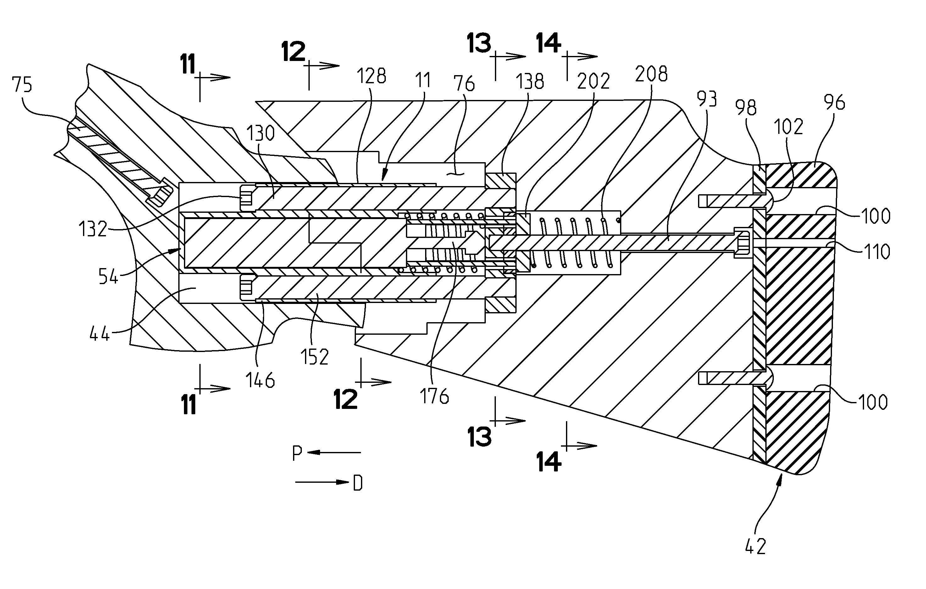
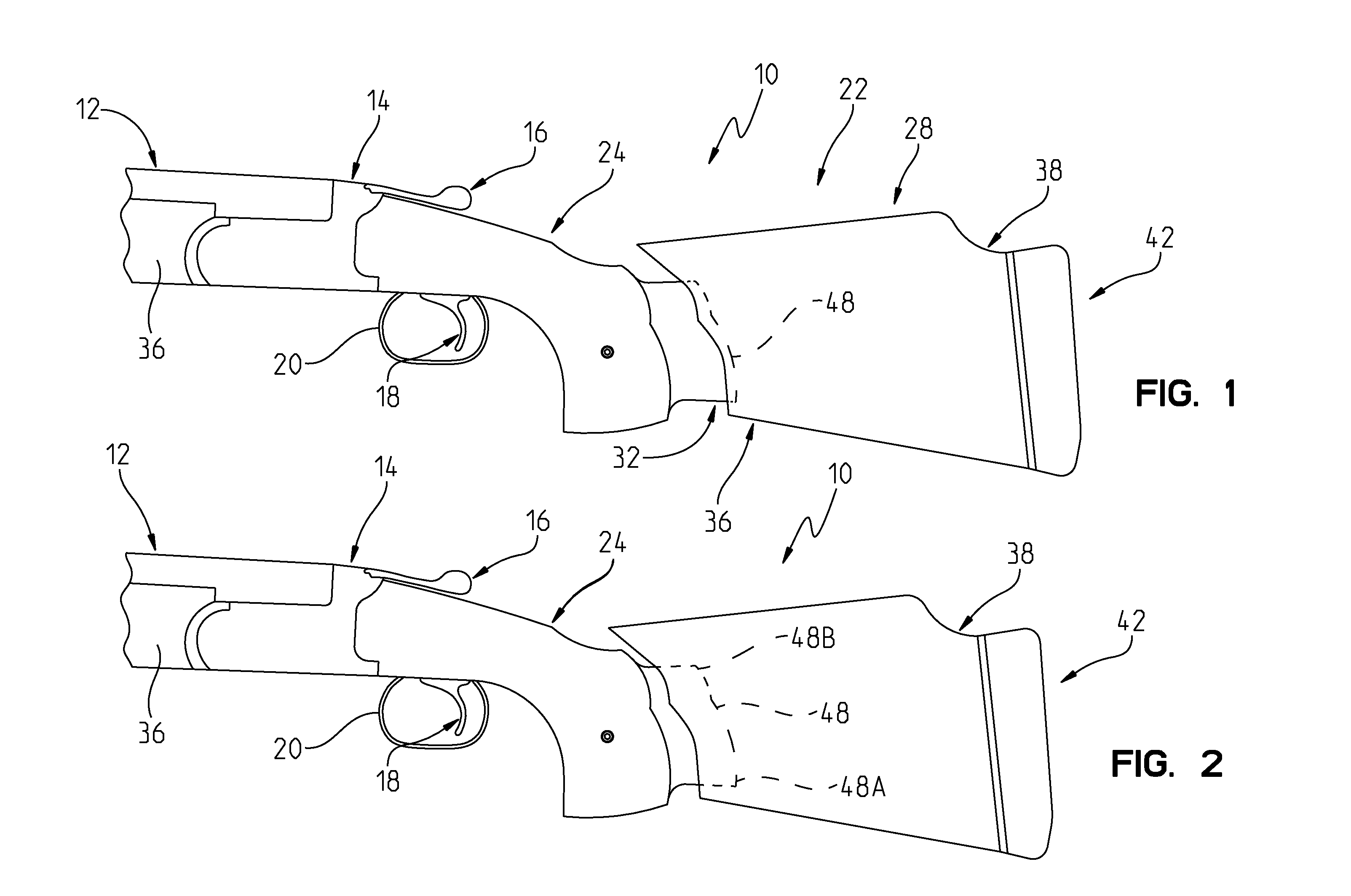
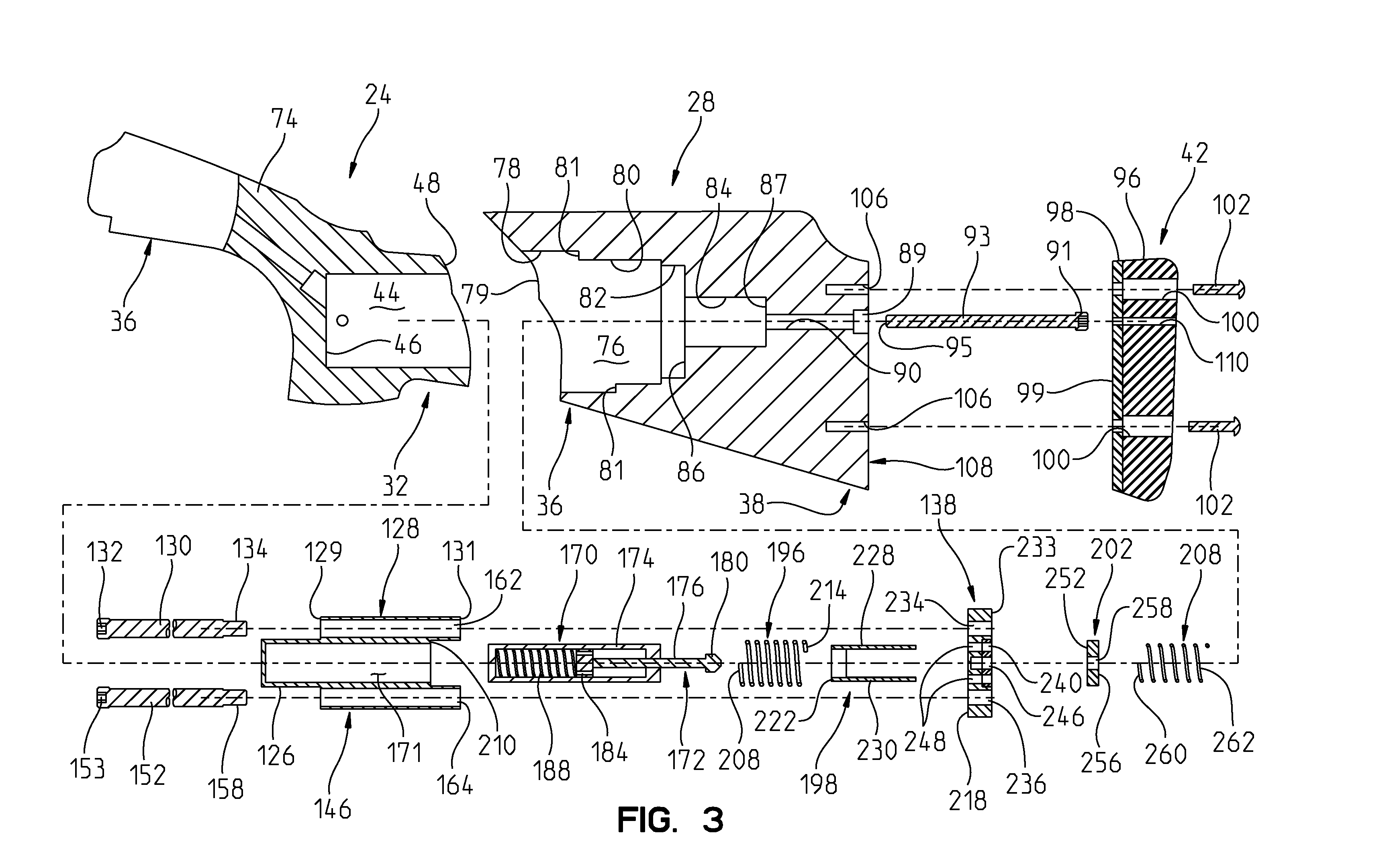
[0051]A firearm is shown in the figures, and in particular FIGS. 1-3 that includes a recoil reducer (FIG. 7) of the present invention.

[0052]A side, exterior view of the firearm 10 (here shown as a rifle 10) is best shown in FIGS. 1 and 2, as including a barrel 12 that is disposed at one end of the firearm 10 and a generally centrally located firing mechanism 14. The firing mechanism 14 includes a magazine portion for containing bullets or shots, a delivery mechanism for delivering the loaded but unfired bullets to the firing chamber, and a firing chamber. The firing chamber is the portion of the firing mechanism that is disposed at the extreme butt end of the barrel, and is the place where the bullet is held prior to the bullet being fired. The tiring mechanism 14 also includes a hammer 16 for striking the bullet thereby detonating the bullet; and a trigger 18 for actuating the hammer 16. In many rifles, a trigger guard 20 partially encases the trigger 18, to prevent the trigger fro...


PUM


Abstract

A recoil reducer device for use with a firearm is provided, that is movable between a rest position and a recoil position. The recoil reducer device includes a firearm stock, including a first stock member having a first stock member cavity, and a second stock member having a second stock member cavity. A recoil reducer is receivable in the first and second stock cavities. The recoil reducer includes a shock absorber including a housing and an axially movable plunger. A slider is provided that includes a first slider member fixedly coupled to the shock absorber, and a second slider member movable with respect to the shock absorber and first stock member. A base member is fixedly coupled to the second slider member and a magnet that is magnetically coupled to the base member.

Description

I. PRIORITY STATEMENT[0001]The instant application claims benefit of Simms, U.S. Provisional Patent Application No. 61 / 199,479 that was filed on 17 Nov. 2008, and which is incorporated herein fully by reference.II. TECHNICAL FIELD OF THE INVENTION[0002]The present invention relates to firearms, and more particularly to a recoil reducer for use in connection with a firearm, to reduce the shock imparted on a user's body by a discharging firearm.III. BACKGROUND OF THE INVENTION[0003]Firearms have been in use for hundreds of years. The two most popular types of firearms include shoulder-mounted firearms, such as shotguns, rifles, and the like; and hand guns, such as pistols. When a firearm discharges its bullet (or shell), the explosion of the gun powder contained in the bullet or shell casing causes the bullet (or load) to be ejected out of the barrel of the pistol or rifle at a high velocity.[0004]Along with the force of the bullet being shot out of the barrel, there exists a rearward...

Claims


Application Information

Patent Timeline
Patent Type & Authority Applications(United States)
IPC IPC(8): F41C23/06
CPCF41C23/14F41C23/08
Inventor SIMMS, NATHANSIMMS, PHIL
Owner SIMMS NATHAN
Why Eureka
Try Eureka