Wideband RF 3D transitions

a wideband rf and transition technology, applied in the field of electromagnetic devices, can solve the problems of high cost and bulkyness of current state-of-the-art automotive radars, and achieve the effect of reducing losses and reducing return losses

Inactive Publication Date: 2010-06-03
TOYOTA MOTOR ENGINEERING & MANUFACTURING NORTH AMERICA
View PDF25 Cites 61 Cited by
  • Summary
  • Abstract
  • Description
  • Claims
  • Application Information

AI Technical Summary

Benefits of technology

[0014]In some examples, the transition via is impedance matched to the antenna feed. The antenna feed may comprise a waveguide, such as a coplanar waveguide (CPW). A (CPW) may comprise a conducting stripe located between a pair of grounded regions, the stripe being separated from the grounded regions by narrow gaps extending along the edges of the stripe. The pair of grounded regions for the CPW may be provided by a ground region extending around the via pad and the conducting stripe of the CPW. The ground region may be tapered to reduce return losses. The ground region may also have a smoothed edge. Shorting vias may be provided between the ground region and a ground plane on the second side of the antenna substrate, for example a ground plane associated with a waveguide (e.g. CPW) connection between the transition via and the RF circuit (and / or the antenna ground plane). In some descriptions, for conciseness, the term CPW is used to indicate the central conducting stripe of the waveguide structure. The antenna feed may comprise a CPW portion, having associated grounded regions, which transitions to a microstrip line as the edges of the grounded regions extend away from the conducting stripe. In some examples, the width of the central stripe of the CPW may be narrower than the that of the microstrip line, which can assist maintenance of a generally constant impedance through the antenna feed. In some examples, the central stripe of the CPW extends through a slot in the ground region. The capacitance of the via pads, combined with the self-inductance of the transition via, can be configured to give a transition impedance (e.g. 50 ohms) that is matched to that of the antenna feed, reducing losses compared with conventional approaches.

Problems solved by technology

However, current state-of-the-art automotive radars are expensive and bulky.

Method used


Image

  • Wideband RF 3D transitions
  • Wideband RF 3D transitions
  • Wideband RF 3D transitions

Examples


Embodiment Construction

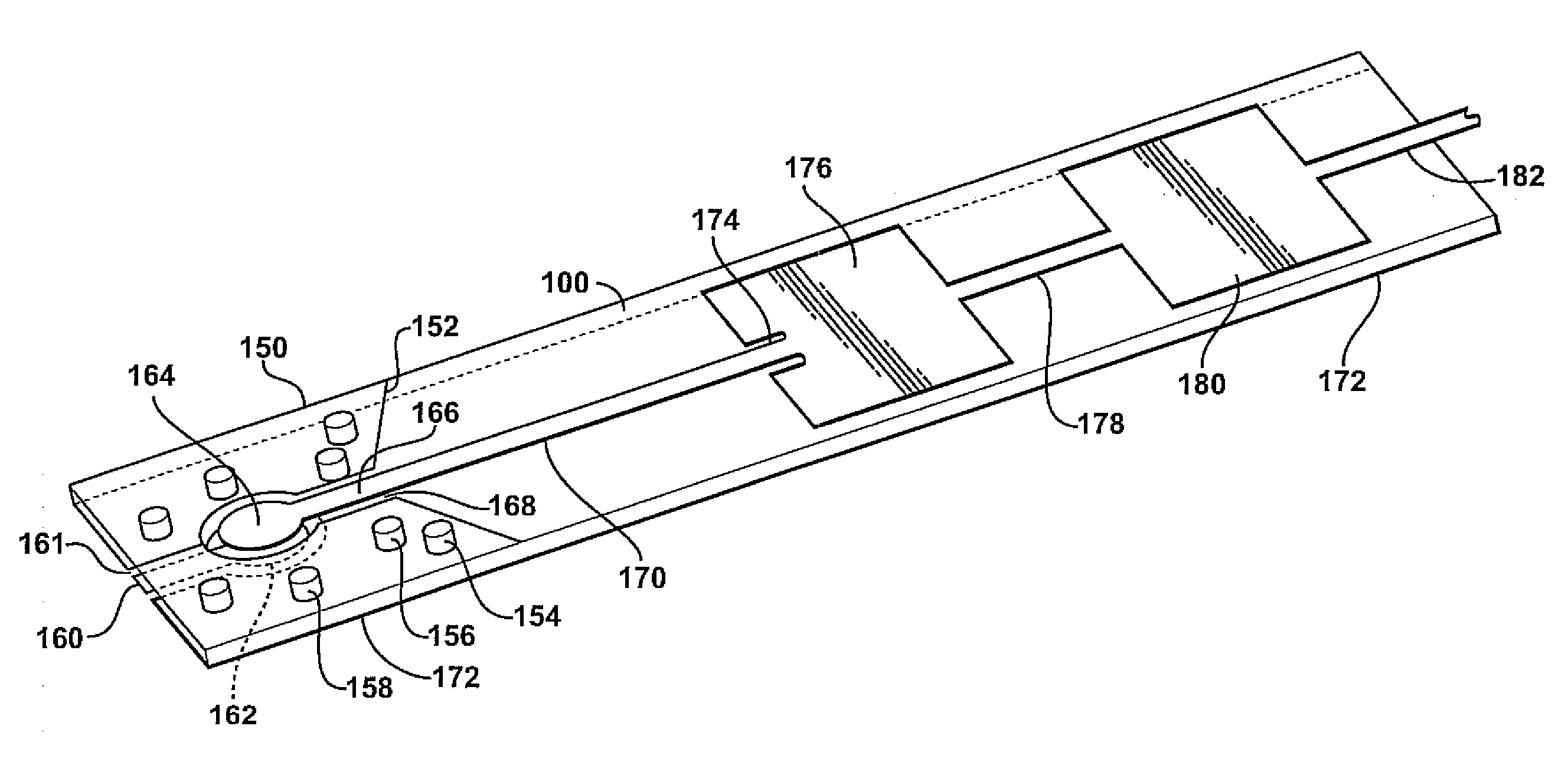
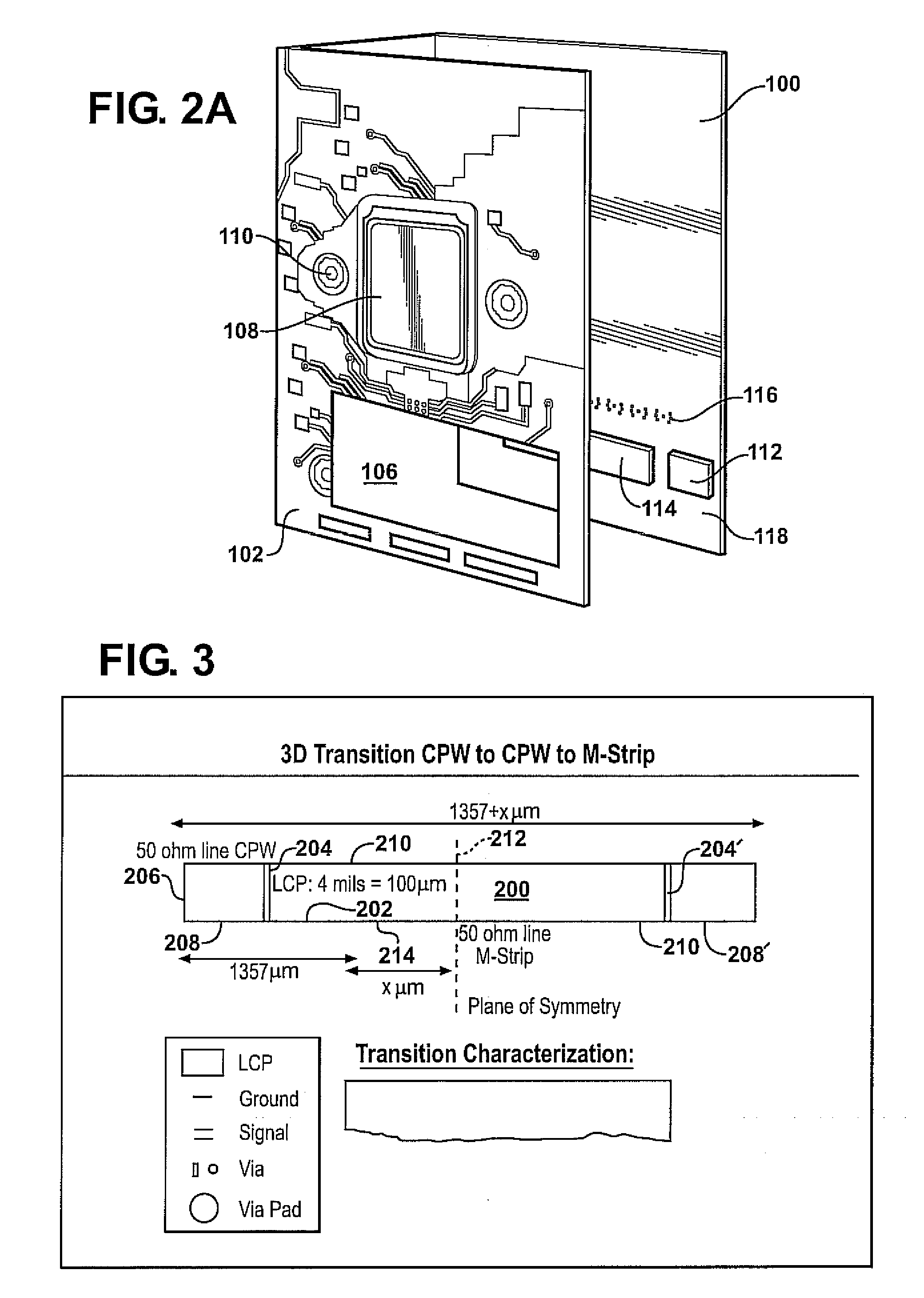
[0029]Examples of the present invention include apparatus and methods related to low cost, high performance transition vias on antenna substrates, in particular low loss RF substrates such as liquid crystal polymer based layers. Improved transitions according to embodiments of the present invention may, for example, be used in a three-dimensional (3D) RF front end of automotive radars. Other applications include any millimeter wave RF front end application, including 60 gigahertz WLAN / WPAN applications, communication systems, W band imaging and the like.

[0030]Examples of the present invention include improved RF front ends with reduced insertion and return loss. RF performance, in some examples, may be improved using a tapered ground plane and / or placing grounding vias in appropriate locations so as to suppress parasitic modes and substantially eliminate radiation loss.

[0031]Conventional automotive radars are relatively expensive and bulky. Conventionally, a metal frame is used to p...


PUM


Abstract

Apparatus and methods according to examples of the present invention include providing an electrical interconnection between an RF circuit and an antenna, the electrical interconnection including a transition via through an antenna substrate. The electrical connection can be configured so as to provide low losses.

Description

FIELD OF THE INVENTION[0001]The invention relates to electromagnetic devices, for example radar antennas.BACKGROUND OF THE INTENTION[0002]Antennas are useful for a variety of applications, for example automotive radar applications. A low cost antenna is highly desirable. However, current state-of-the-art automotive radars are expensive and bulky.SUMMARY OF THE INVENTION[0003]Embodiments of the present invention relate to microwave applications, in particular millimeter wave antennas including automotive radar antennas. Examples of the present invention include improved apparatus and methods for 3D transitions between an RF circuit and an antenna, in particular using a low loss RF antenna substrate for microwave and / or millimeter wave applications. Example applications include improved 77 gigahertz and 77-81 gigahertz automotive radars, and 94 GHz mm-wave imaging apparatus.[0004]Examples of the present invention include improved electrical interconnections between an antenna and RF c...

Claims


Application Information

Patent Timeline
Patent Type & Authority Applications(United States)
IPC IPC(8): H01Q1/38H01Q1/48H01Q1/50
CPCH01P5/028H01Q21/065H01Q21/0037H01L2223/6627H01L2223/6677H01L2224/16227H01L2224/48227H01Q13/206
Inventor MARGOMENOS, ALEXANDROSRIDA, AMIN
Owner TOYOTA MOTOR ENGINEERING & MANUFACTURING NORTH AMERICA
Why Eureka
Try Eureka