Surface-mounted over-current protection device

a protection device and surface mount technology, applied in emergency protective arrangements, cell components, cell components, etc., can solve the problems of reducing the performance of the smd device, and reducing the resistance of the conductive composite. , to achieve the effect of low resistance, low resistance and high hold curren

Active Publication Date: 2010-06-03
POLYTRONICS TECH
View PDF20 Cites 37 Cited by
  • Summary
  • Abstract
  • Description
  • Claims
  • Application Information

AI Technical Summary

Benefits of technology

[0015]With the relatively low resistivity (i.e., below 0.2 Ω-cm) of the PTC material layer, the covered area of the surface-mounted over-current protection device of the present invention can be shrunk below 50 mm2, preferably below 25 mm2 (corresponding to the SMDs with form factor of 1812, 1210, 1206, 0805, 0603, or 0402), and the objectives of low resistance and high hold current can still be achieved.

Problems solved by technology

Even though the low resistivity mentioned above is achieved, the PTC conductive composite often loses the characteristic of voltage endurance.
Since the conductivity of carbon black is relatively low (i.e., relatively high resistance), if carbon black is applied to a surface mount device (SMD) with fixed covered area, the hold current of the SMD is limited to certain level due to the resistance limitation of carbon black.
Although a multi-layer PTC structure could be used to increase the hold current, SMD device performance is eventually limited due to the limitation of total height as well as the number of PTC layers of the SMD device.

Method used


Image

  • Surface-mounted over-current protection device
  • Surface-mounted over-current protection device
  • Surface-mounted over-current protection device

Examples


first embodiment

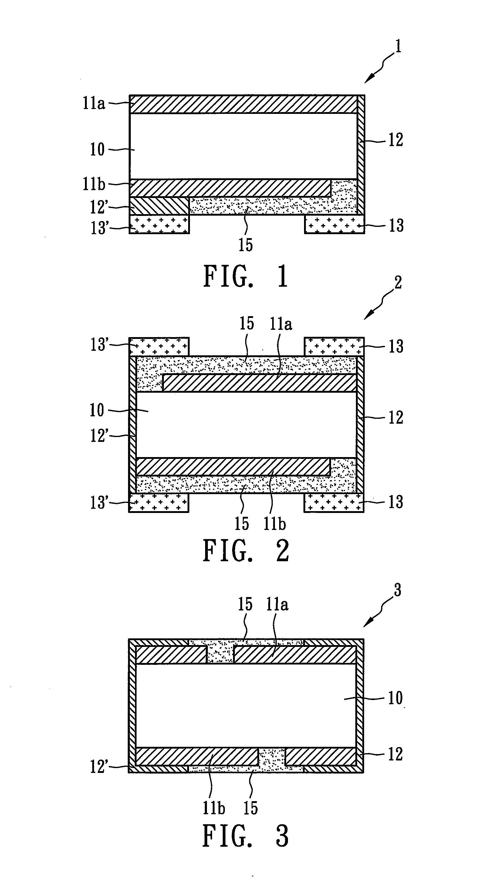
[0021]FIG. 1 illustrates the surface-mounted over-current protection device 1, which is suitable to adhere to a substrate (not shown). A first metal electrode 13 and a second metal electrode 13′ corresponding to the first metal electrode 13 are usually located on the same plane. The surface-mounted over-current protection device 1 could be designed to contain only one electrode set comprising the first metal electrode 13 and the second metal electrode 13′ such that only one surface thereof could adhere to the surface of the substrate. The design in FIG. 1 is usually applied to a narrow space and meets the requirements of one-way heat conduction or one-way heat insulation. In the current embodiment, the first metal electrode 13, a first metal conductor 12, a first metal foil 11a, a PTC material layer 10, a second metal foil 11b, a second metal conductor 12′, and the second metal electrode form a conductive circuit to connect an external device (not shown) and a power source (not show...

third embodiment

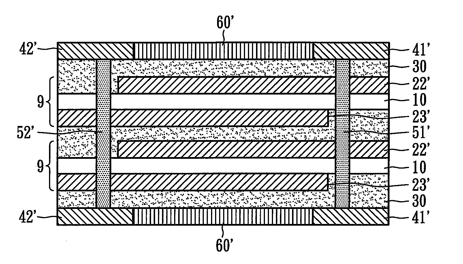
[0023]FIG. 3 illustrates the surface-mounted over-current protection device 3, in which the first metal conductor 12 and the second metal conductor 12′ are developed by metallic electroplating on surfaces of the surface-mounted over-current protection device 3 to form wrap-around electrical conductors. In addition, the first and the second metal conductors 12 and 12′ could be connected to the first and the second metal foils 11a and 11b and metal electrodes (not shown) by soldering, electroplating, and then reflow or heat-curing. In the current embodiment, the first and the second metal conductors 12 and 12′ can also be formed by first forming micro holes and then plating-through-hole or metal filling.

fourth embodiment

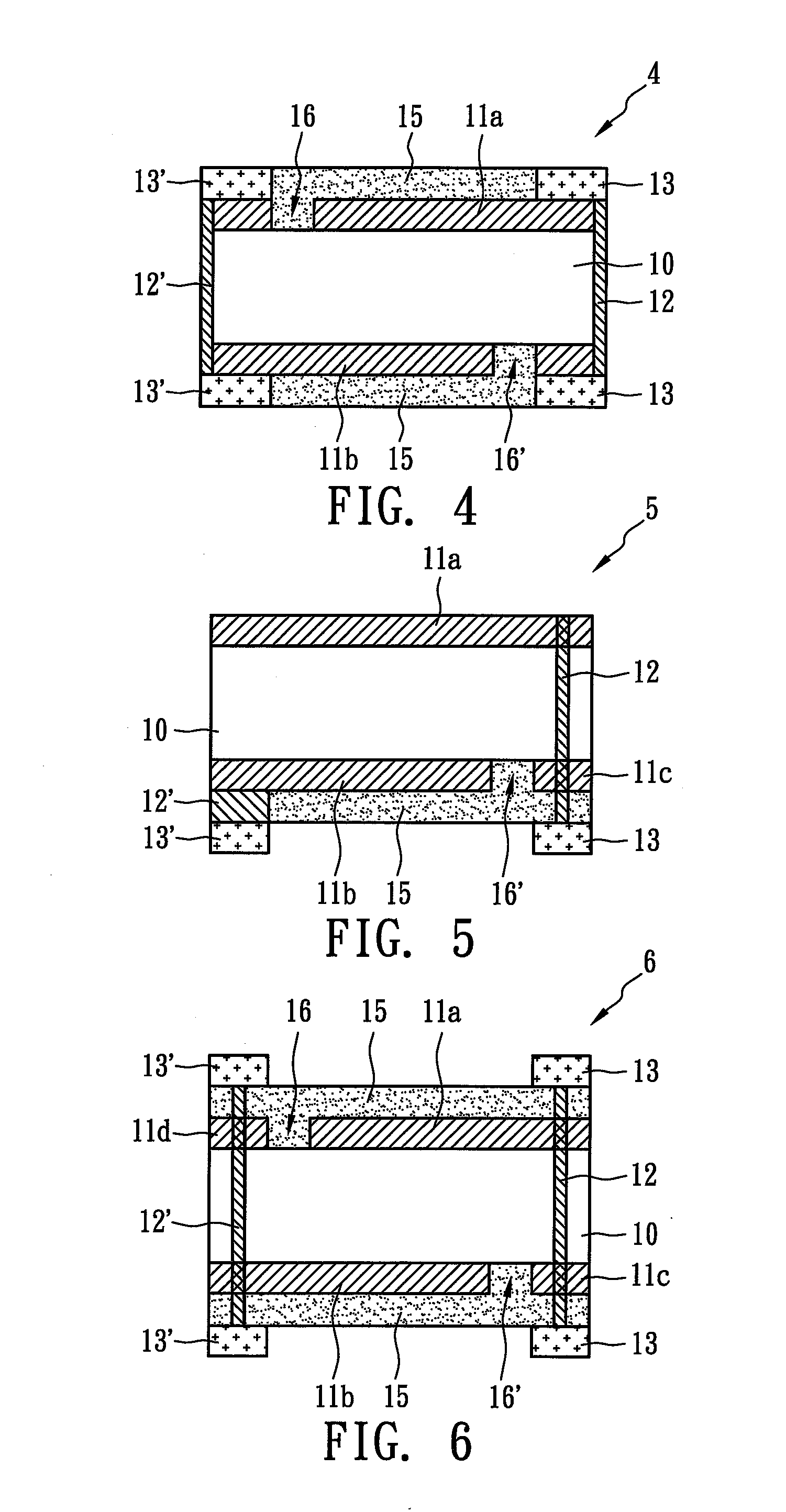
[0024]FIG. 4 illustrates the surface-mounted over-current protection device 4, in which the first metal conductor 12 and the second metal conductor 12′ combine the first metal electrode 13 and the second metal electrode 13′, respectively, to directly form metal electrodes. The first metal foil 11a is formed by etching and is electrically insulated from the second metal electrode 13′ and the second metal conductor 12′ by an etching line 16 (or etching area). Similarly, the second metal foil 11b is formed by etching and is electrically insulated from the first metal electrode 13 and the first metal conductor 12 by an etching line 16′ (or etching area).


PUM

PropertyMeasurementUnit
particle size distributionaaaaaaaaaa
resistanceaaaaaaaaaa
widthaaaaaaaaaa

Abstract

A surface-mounted over-current protection device with positive temperature coefficient (PTC) behavior is disclosed. The surface-mounted over-current protection device comprises a first metal foil, a second metal foil corresponding to the first metal foil, a PTC material layer stacked between the first metal foil and the second metal foil, a first metal electrode, a first metal conductor electrically connecting the first metal foil to the first metal electrode, a second metal electrode corresponding to the first metal electrode, a second metal conductor electrically connecting the second metal foil to the second metal electrode, and at least one insulated layer to electrically insulate the first metal electrode from the second metal electrode. The surface-mounted over-current protection device, at 25° C., indicates that a hold current thereof divided by the product of a covered area thereof and the number of the conductive composite module is at least 0.16 A/mm2.

Description

CROSS-REFERENCE TO A RELATED APPLICATION[0001]This application is a Continuation-In-Part (CIP) of U.S. patent application Ser. No. 11 / 478,604 filed on Jul. 3, 2006.BACKGROUND OF THE INVENTION[0002]1. Field of the Invention[0003]The present invention relates to a surface-mounted over-current protection device and more particularly, to a surface-mounted over-current protection device exhibiting a small covered area, high hold current, and positive temperature coefficient (FTC) behavior.[0004]2. Description of the Prior Art[0005]The resistance of a PTC conductive composite is sensitive to temperature change. When a PTC device containing PTC conductive composite operates at room temperature, its resistance remains at a low value so that the circuit elements can operate normally. However, if an over-current or an over-temperature situation occurs, the resistance of the PTC device will immediately increase at least ten thousand times (over 104 ohm) to a high resistance state. Therefore, t...

Claims


Application Information

Patent Timeline
Patent Type & Authority Applications(United States)
IPC IPC(8): H02H9/02H01C7/13H01M50/572H01M50/574
CPCH01C1/1406H01C7/021H01M10/052H01M2/34H01M2/348H01C7/18Y02E60/10H01M50/572H01M50/581H01M50/574
Inventor WANG, SHAU CHEWCHU, FU HUA
Owner POLYTRONICS TECH
Why Eureka
Try Eureka