Ventless Mask CPAP System

a mask and cpap technology, applied in the direction of valves, respirators, mechanical equipment, etc., can solve the problems of increasing the flow of the vent, increasing the impedance of the mask vent, and constantly proving to be a complex design issue, etc., to reduce the impedance, increase the pressure differential over current methods, and increase the pressure differential

Active Publication Date: 2010-06-17
RESMED LTD
View PDF18 Cites 114 Cited by
  • Summary
  • Abstract
  • Description
  • Claims
  • Application Information

AI Technical Summary

Benefits of technology

[0049]Another aspect of the invention relates to reducing the impedance and/or increasing the pressure differential over current methods between the region of exhaled/exhausted gas from a patient (externally adjacent to a patient's airways) to atmosphere (environment surrounding the patient) whilst venting the patient's exhausted gas to a remote vent location (relative to the mask interface) thus moving noise or irritating airflow source (e.g. jetting) a significant distance from the patient and/or bed partner's ears/head or otherwise to a suitable location where the noise and jetting source may be suitably attenuated.
[0050]In still another aspect, the invention relates to increasing the pressure differential at a vent between the inside of a mask and atmosphere to increase flow and therefore washout a greater

Problems solved by technology

Mask vents have constantly proved to be a complex design issue for engineers who are required to develop vents that are quiet for patients and bed partners, flush out adequate CO2, and do not ‘jet’ irritating streams of air onto the body or bed partner due to poor dissipation or vented air direction.
This traditional vent location has provided an ideal location for CO2 washout but poor location for noise as it is relatively close to the patient's ears.
An undesirable effect typically results with increased vent flow, that is vent noise.
Adequate venting is generally a design issue at lower treatment pressures (say 4 cm water) where CO2 rebreathing is more likely.
These vents, though lower in vent flow, are still an irritating noise source near the patient's (and bed partner's) ears.
Designing a mask system to meet this requirement represents a significant design challenge with many tradeoffs such as noise and vented direction (and air jetting).
The complexity of the mask design may also affect maintenance such as ease of cleaning and may negatively influence the mask configuration and appearance.
Generally, increased volume results in increased rebreathing.
A significant development effort is therefore required before a mask interface can be marketed and safely used on a patient.
This results in a common irritating noise source in close proximity to a user (say within

Method used


Image

  • Ventless Mask CPAP System
  • Ventless Mask CPAP System
  • Ventless Mask CPAP System

Examples


Embodiment Construction

[0070]Preferred or exemplary embodiments of the invention will be described in reference to FIGS. 1-15. Initially, only a general description of the components for preferred embodiments will be described, and this will be followed with a further description of features, advantages and other options.

[0071]Aspects of the air delivery methods or systems described below may be incorporated into other systems such as those described in U.S. Patent Application No. 60 / 775,334, entitled Mask Pressure Regulation in CPAP Treatment and Assisted Respiration by Dynamic Control of Mask Vent Flow and filed Feb. 22, 2006 the entirety incorporated herein by reference.

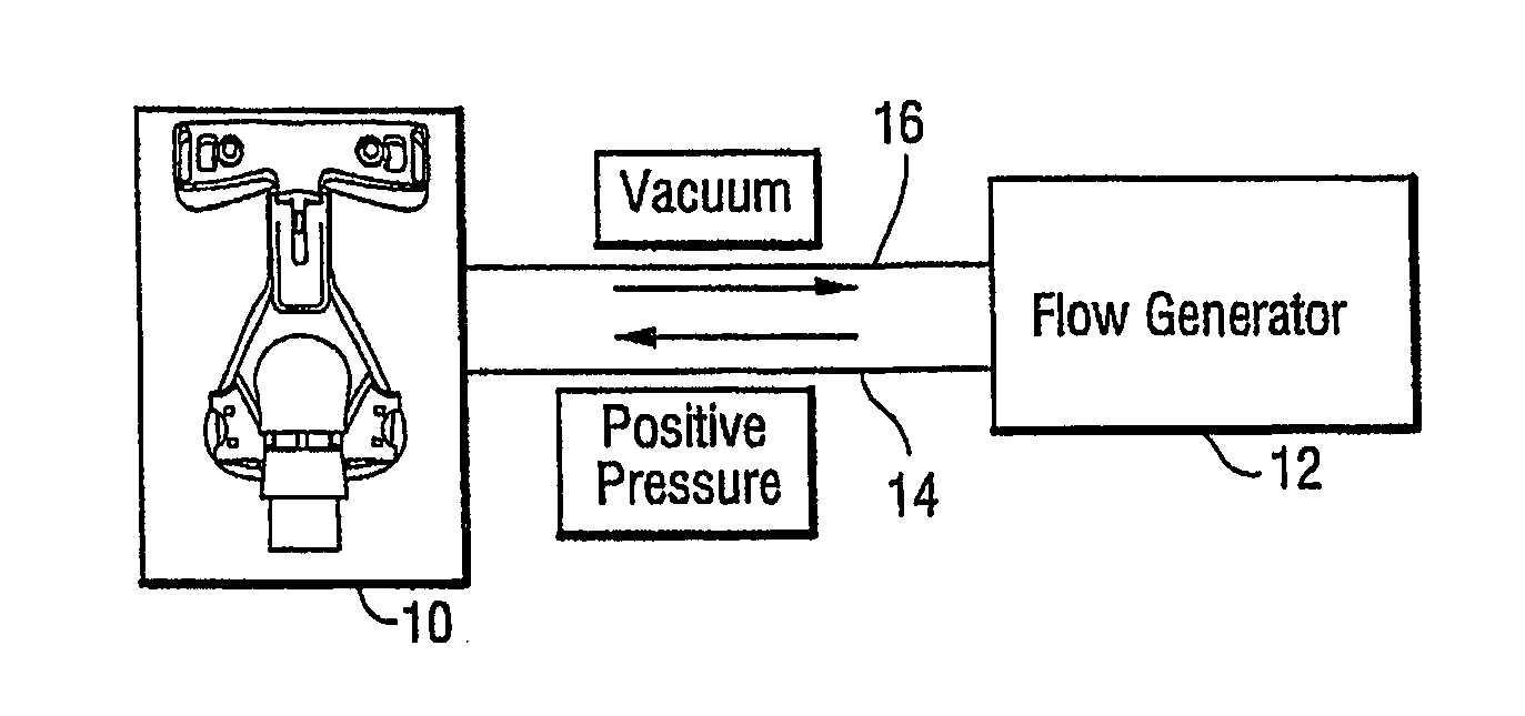
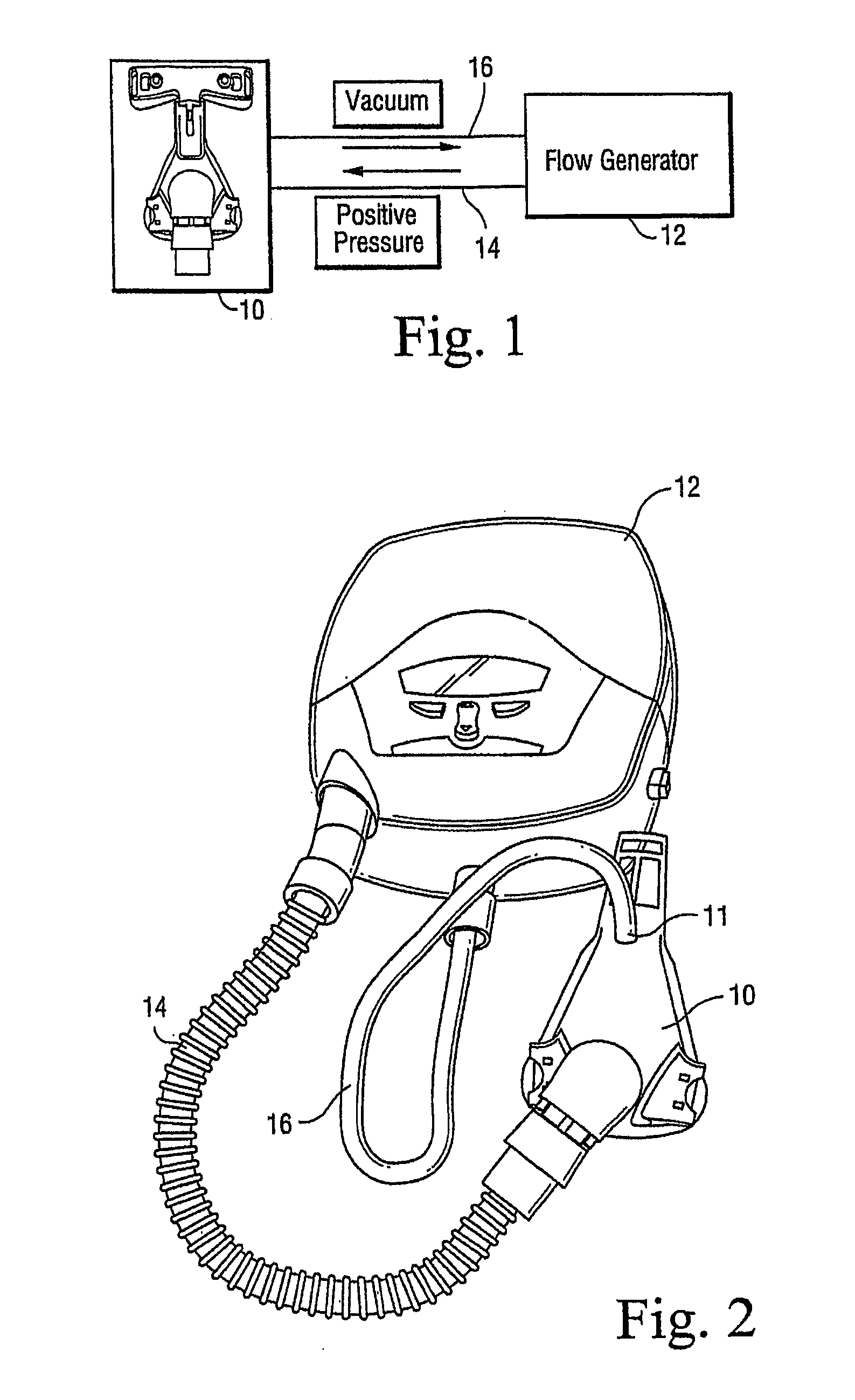
[0072]FIG. 1 shows an assembly according to a first embodiment of the present invention. The assembly includes a mask 10 in the form of a full face mask, although nasal mask, nasal cannula, prongs, nozzles or puffs are also within the scope of the present invention. Mask 10 is in communication with the flow generator 12 via a positive p...


PUM


Abstract

A CPAP or other ventilation system includes a mask, a flow generator, a positive or high pressure line to provide positive or high pressure air from the flow generator to the mask and a vacuum or return line provided to actively extract exhaled gas from the breathing chamber and/or the air delivery conduit of the mask. The vacuum or return line includes a vent outlet preferably positioned remote from the mask.

Description

CROSS-REFERENCE TO RELATED APPLICATIONS[0001]This application claims the benefit of U.S. Provisional Application Nos. 60 / 667,052, filed Apr. 1, 2005, 60 / 706,430, filed Aug. 9, 2005, and 60 / 775,334, filed Feb. 22, 2006 each expressly incorporated by cross-reference in its entirety.STATEMENT REGARDING FEDERALLY SPONSORED RESEARCH OR DEVELOPMENT[0002]N / ABACKGROUND OF THE INVENTION[0003]The primary non-invasive method of treating Obstructive Sleep Apnea (OSA) has traditionally used a Continuous Positive Airway Pressure (CPAP) device (also generically known as a Flow Generator), an interface to the patient's airway, and an interconnecting tube or pipe to supply a gas. There have also been further variations to this system including a flow generator that is integrated with a mask interface without an interconnecting tube (see U.S. Provisional Application No. 60 / 505,718 filed Sep. 25, 2003, and International Application No. PCT / AU04 / 01309, filed Sep. 27, 2004, each incorporated herein by r...

Claims


Application Information

Patent Timeline
IPC IPC(8): A61M16/06A61M16/00
CPCA61M16/00A61M16/0066A61M16/06A61M2016/0027A61M2016/0039A61M2206/14A61M16/22A61M16/0009A61M16/0633A61M16/0672A61M16/0883A61M16/202A61M2230/432A61M16/1055A61M16/0012A61M16/0093A61M16/1065A61M16/0825A61M16/0622A61M16/024
Inventor SELVARAJAN, KARTHIKEYANKWOK, PHILIP RODNEYKENYON, BARTON JOHNGREGORY, BRUCE DAVIDREED, NICHOLAS JEROMEBLUNSDEN, CHRISTOPHER KINGSLEY
Owner RESMED LTD
Why Eureka
Try Eureka