Exhaust heat recovery system

a heat recovery system and exhaust heat technology, applied in the direction of machines/engines, combustion air/fuel air treatment, light and heating equipment, etc., can solve the problems of stock fuel not being efficiently separated, the temperature of other systems of internal combustion engines requiring a rise of temperature, and the heat energy not recovered by the heat pipe, etc., to achieve a certain degree of heat recovery, maintain the warm-up performance of the exhaust purification catalyst, and recover at least a certain amount of exhaust heat

Inactive Publication Date: 2010-06-24
EXXON RES & ENG CO +1
View PDF11 Cites 14 Cited by
  • Summary
  • Abstract
  • Description
  • Claims
  • Application Information

AI Technical Summary

Benefits of technology

[0018]According to the present invention, since the second heat transport device recovers the heat of the exhaust gas at the downstream side of the exhaust purification catalyst, it is possible to maintain the warm-up performance of the exhaust purification catalyst. Further, since the first heat transport device recovers the heat of the exhaust gas at the exhaust purification catalyst or its upstream side, even at the time of the cold start of the internal combustion engine, it is possible to recover a certain extent of heat. Therefore, according to the present invention, by suitably setting the heat transport capacities of the first heat transport device and second heat transport device, it is possible to recover at least a certain amount of exhaust heat while maintaining the warm-up performance of the exhaust purification catalyst.

Problems solved by technology

However, if setting the work start temperature of the heat pipe to a temperature higher than the activation temperature of the exhaust purification catalyst like in the exhaust heat recovery system described in Japanese Patent Publication (A) No. 2005-264916, when the temperature of the exhaust gas flowing into the exhaust purification catalyst is lower than the catalyst activation temperature, heat energy is not recovered by the heat pipe.
Therefore, during this time, it is not possible to raise the temperature of other systems of the internal combustion engine requiring a rise of temperature.
However, if using an exhaust heat recovery system such as described in the above-mentioned Japanese Patent Publication (A) No. 2005-264916, sometimes the temperature of the stock fuel flowing into the fuel separation system rises to the certain temperature or more and therefore the stock fuel cannot be efficiently separated.
If it is not possible to efficiently separate the stock fuel in this way, it is not possible to maintain the optimum combustion of the internal combustion engine.

Method used


Image

  • Exhaust heat recovery system
  • Exhaust heat recovery system
  • Exhaust heat recovery system

Examples


first embodiment

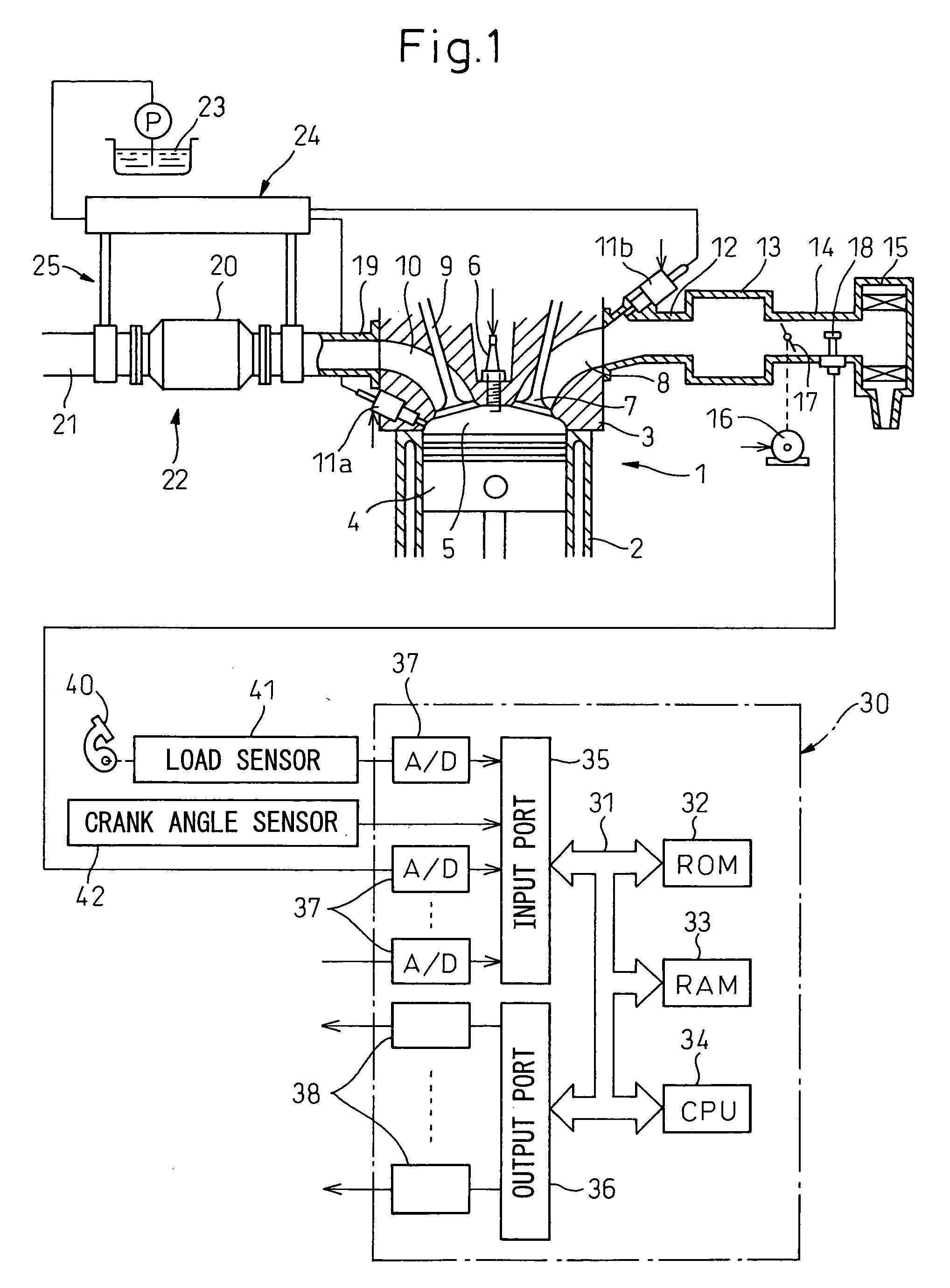
[0028]Below, referring to the drawings, an exhaust heat recovery system of the present invention will be explained in detail. FIG. 1 is a side cross-sectional view of a spark ignition type internal combustion engine at which an exhaust heat recovery system is mounted.

[0029]Referring to FIG. 1, 1 indicates an engine body, 2 a cylinder block, 3 a cylinder head, 4 a piston, 5 a combustion chamber, 6 a spark plug arranged at the center of the top of the combustion chamber 5, 7 an intake valve, 8 an intake port, 9 an exhaust valve, and 10 an exhaust port. On the peripheral region of each cylinder inner wall of the cylinder head 4, a fuel injector 11a for injecting fuel directly into the combustion chamber 5 (below referred to as “in-cylinder fuel injector”) is arranged. Each intake port 8 is connected through an intake branch pipe 12 to a surge tank 13. At each intake branch pipe 12, a fuel injector 11b for injecting fuel toward the inside of the corresponding intake port 8 (below referr...

fourth embodiment

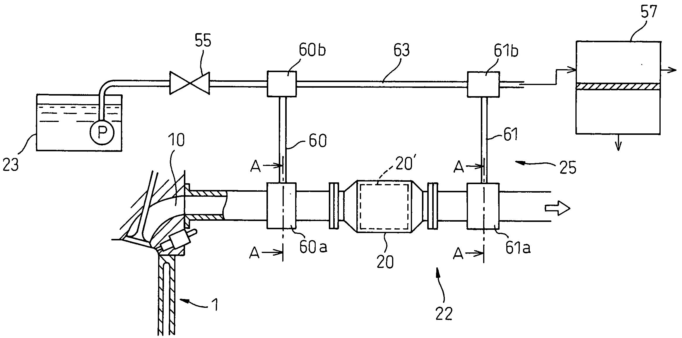
[0086]That is, as shown in FIG. 8, in the fourth embodiment, two fuel feed pipes 63a, 63b are provided between the stock fuel tank 23 and the separation unit 57. The fuel feed pipes 63a, 63b are provided with flow control valves 55a, 55b, respectively. The heat exchange part 60b of the upstream side heat pipe 60 is attached to the first fuel feed pipe 63a, while the heat exchange part 61b of the downstream side heat pipe 61 is attached to the second fuel feed pipe 63b.

third embodiment

[0087]In the present embodiment, when the temperature of the downstream side heat pipe 61 is lower than a certain fixed reference temperature, only the flow control valve 55a provided at the first fuel feed pipe 63a is opened. The flow control valve 55b provided at the second fuel feed pipe 63b is not opened. On the other hand, when the temperature of the downstream side heat pipe 61 is the reference temperature or more, the two flow control valves 55a, 55b are opened. Due to this, in the same way as the third embodiment, it is possible to efficiently supply the heat of the exhaust gas to the stock fuel flowing into the separation unit 57.

[0088]Note that in the present embodiment as well, it is also possible to adjust the opening degree of the second flow control valve 55b in accordance with the temperature of the downstream side heat pipe 61 and the flow rate of the stock fuel to be supplied from the stock fuel tank 23 to the separation unit 57 in the same way as the third embodime...


PUM


Abstract

An exhaust heat recovery system 25 provided with a plurality of heat pipes 60, 61 provided with heat recovery parts 60a, 61a and heat exchange parts 60b, 61b. The heat pipes recover heat from exhaust gas exhausted from an internal combustion engine at the heat recovery parts and transfer this recovered heat to an object to be heated at the heat exchange parts. The heat recovery part 60a of the first heat pipe 60 recovers heat from the exhaust gas at an exhaust purification catalyst 20′ provided in an engine exhaust passage or its upstream side. The heat recovery part 61b of the second heat pipe 61 recovers heat from the exhaust gas at the downstream side of the exhaust purification catalyst. Due to this, there is provided an exhaust heat recovery system which can recover at least a fixed amount of exhaust heat at all times while maintaining a warm-up performance of the exhaust purification catalyst.

Description

TECHNICAL FIELD[0001]The present invention relates to an exhaust heat recovery system.BACKGROUND ART[0002]The exhaust gas exhausted from an internal combustion engine in general is higher in temperature than the atmospheric temperature and therefore contains large heat energy. Therefore, an exhaust heat recovery system has been proposed which recovers the heat energy included in the exhaust gas and utilizes the recovered heat energy to raise the temperature of other systems of the internal combustion engine or converts the heat energy to electrical energy for storage in a battery.[0003]As such an exhaust heat recovery system, for example, it is known to attach a heat pipe to a component part of the exhaust system of an internal combustion engine and attach a thermoelectric conversion element to this heat pipe (for example, Japanese Patent Publication (A) No. 2005-264916). By using such a heat pipe, the heat of the exhaust system can be transferred to the thermoelectric conversion el...

Claims


Application Information

Patent Timeline
Patent Type & Authority Applications(United States)
IPC IPC(8): F01N3/02F28D7/00
CPCF01N5/02F01N2240/02F02M1/165F02M31/005F02M31/20Y02T10/16F28D15/0275F28D21/0003F28F1/12Y02T10/126F02M37/0064Y02T10/12
Inventor PARTRIDGE, RANDALL D.GUPTA, RAMESHSUGIYAMA, KOUSEKI
Owner EXXON RES & ENG CO
Why Eureka
Try Eureka