Apparatus and Method for Cooling Part Cake in Laser Sintering

a technology of laser sintering and parts cake, applied in the field of laser sintering, can solve the problem of system being unavailable for subsequent builds, and achieve the effect of rapid cooling of parts cak

Inactive Publication Date: 2010-06-24
3D SYST INC
View PDF10 Cites 55 Cited by
  • Summary
  • Abstract
  • Description
  • Claims
  • Application Information

AI Technical Summary

Benefits of technology

[0007]The invention provides methods and apparatus for cooling a part cake containing a build produced by laser sintering in which the part cake is compressed about the build to allow the un-fused powder to support the build against distortion during

Problems solved by technology

A newly formed build may require several hours or days to cool and, as a result, the laser sintering system

Method used


Image

  • Apparatus and Method for Cooling Part Cake in Laser Sintering
  • Apparatus and Method for Cooling Part Cake in Laser Sintering
  • Apparatus and Method for Cooling Part Cake in Laser Sintering

Examples


Embodiment Construction

[0027]The invention will now be described in more detail with reference to the accompanying drawings, in which multiple embodiments are shown. This invention may, however, be embodied in different forms and should not be construed as limited to the embodiments set forth herein. Rather, these embodiments are provided so that this disclosure will be thorough and complete and will fully convey the scope of the invention to those skilled in the art.

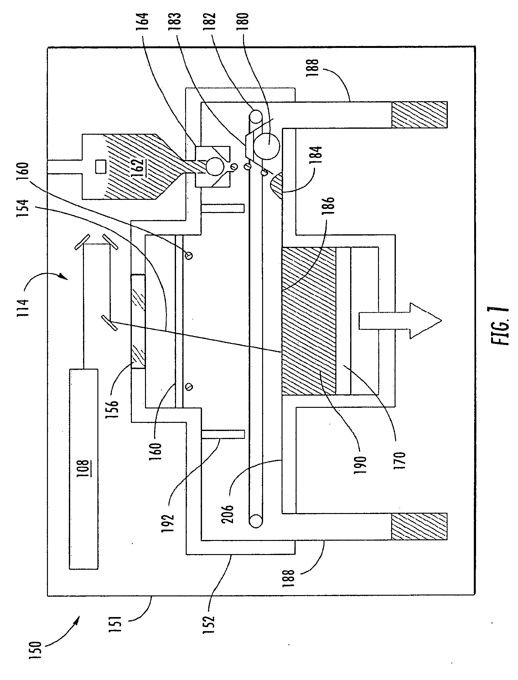
[0028]FIG. 1, shown generally as the numeral 150, illustrates a conventional laser sintering system. An outer skin 151 of an industrial design surrounds the working system. An optics scanning system 114 directs a laser beam 154 from laser 108. Laser beam 154 enters through a laser window 156 that isolates laser 108 and optics 114 from the higher temperature environment inside a process chamber 152. Radiant heating elements 160 provide heat to target area 186 and to the areas immediately next to the target area. These radiant heaters 160 can b...


PUM

PropertyMeasurementUnit
Fractionaaaaaaaaaa
Fractionaaaaaaaaaa
Flow rateaaaaaaaaaa

Abstract

A part cake defining a build produced by laser sintering and the surrounding unfused powder is contained in an enclosure, aid the enclosure includes displaceable wall portions for compressing the part cake to support the build against distortion during rapid cooling from a cooling fluid. The enclosure enables the part cake to be quickly and reliably cooled either within the laser sintering system or outside the laser sintering system. A source of cooling fluid connects to the enclosure and a lid holds the part cake in place as cooling fluid is forced through the pore volume of the cake. An inert gas blanket apparatus is also provided to reduce or prevent oxidation of the part cake and/or to cool the part cake. Once the part cake is cooled, the build produced by laser sintering may be removed from the part cake.

Description

FIELD OF THE INVENTION[0001]This invention relates to laser sintering for the formation of three-dimensional objects from fusible powders and more particularly relates to the cooling of such objects after the sintering has been completed.BACKGROUND OF THE INVENTION[0002]Laser sintering is a solid imaging process for building three-dimensional objects, layer-by-layer, from a working medium utilizing sliced data sets representing cross sections of the object to be formed. Typically an object representation is initially provided by a computer aided design (“CAD”) system. The laser sintering system dispenses a thin layer of heat-fusible powder, normally a fusible polymer powder, polymer coated metal, metal, or ceramic, over a bed of the powder commonly referred to as the “part cake.” The laser sintering system applies thermal energy to melt those portions of the powder corresponding to a cross-section of the article being built in that powder layer. Lasers typically supply the thermal e...

Claims


Application Information

Patent Timeline
IPC IPC(8): B27N3/00B29C35/08F28F1/00
CPCB29C35/16B29C67/0077B29C2035/0838B29C2791/005B29C2035/1666B29C2035/1683B29C2035/1658B29C64/153B33Y40/00B33Y10/00B33Y30/00B33Y40/20
Inventor MCALEA, KEVIN PATRICKPANG, THOMAS HSINGTUMMALA, PRAVEEN
Owner 3D SYST INC
Why Eureka
Try Eureka