A method for cooling air and devices

a technology of cooling gas and cooling air, applied in the direction of positive displacement liquid engine, lighting and heating apparatus, electric generator control, etc., can solve the problem of gas becoming colder as it accelerates

Active Publication Date: 2010-07-01
HIRSHBERG ISRAEL
View PDF3 Cites 19 Cited by
  • Summary
  • Abstract
  • Description
  • Claims
  • Application Information

AI Technical Summary

Benefits of technology

[0026]Still another aspect of the invention is the incorporation of water drain sy

Problems solved by technology

The kinetic energy added to the gas is on the expense of the gas

Method used


Image

  • A method for cooling air and devices
  • A method for cooling air and devices
  • A method for cooling air and devices

Examples


Embodiment Construction

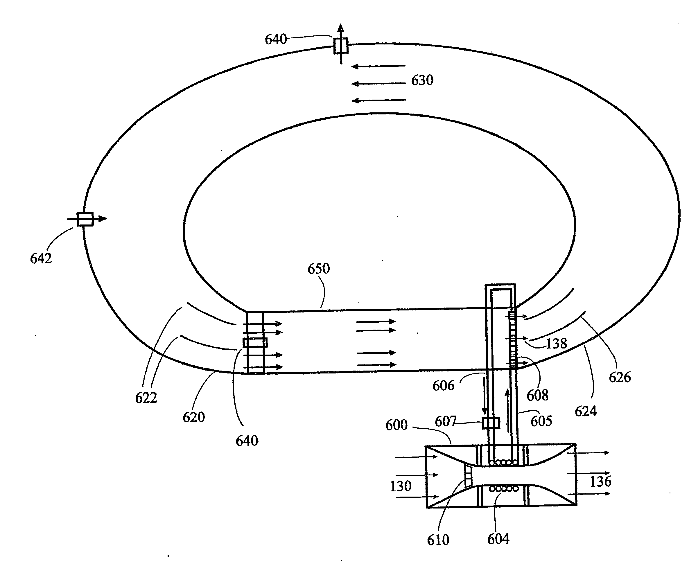
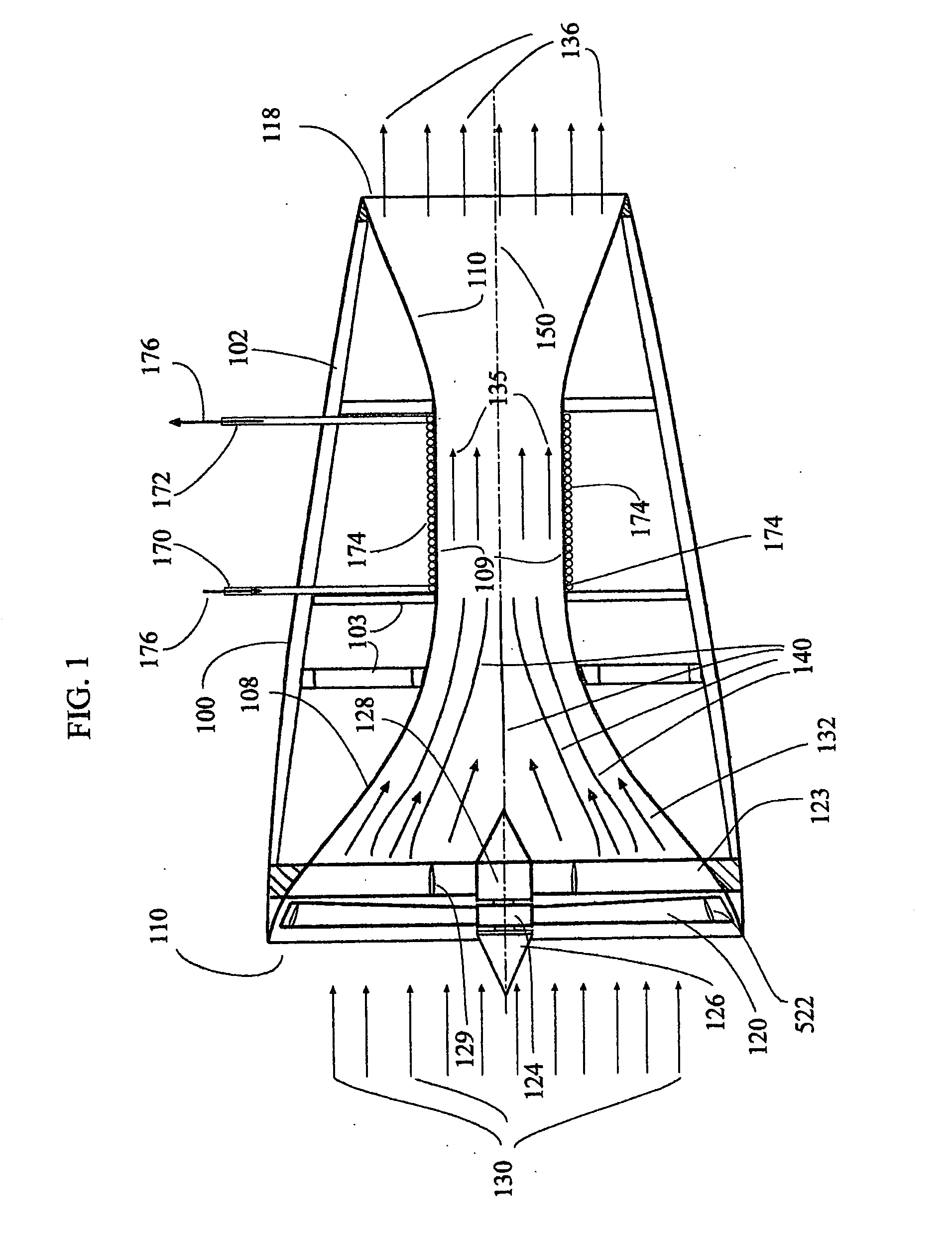
[0036]The invention disclosed here is a method and devices that use gas like air as a refrigerant for air-condition purposes. Due to the physical law of continuity, as the nozzle cross-section decreases the gas must accelerates. Thus the kinetic energy of the gas increases. In an adiabatic flow the kinetic energy comes on the expense of the gas internal energy CpT, where Cp is the gas constant pressure specific heat and T is the absolute temperature. At the nozzle throat, the gas has maximum speed and consequently minimum temperature. It is possible to use air at 50° Celsius and accelerate it to speed of sound at the throat, where its temperature will be: 0.834(273+50)° C.=269.4° K., i.,e., −3.8° C. This low temperature is good for air-condition system even it hottest countries in the world. The cold airflow cools the nozzle skin so we can use it to absorb heat from a heat exchanger and use the cooled flow within the heat exchanger to cool remote spaces or basically anything. The us...


PUM


Abstract

A method of constructing self-powered air-conditioner comprises a convergent divergent nozzle where powered fan pushes air into said nozzle. While the pushed air accelerates toward the nozzle throat it becomes colder as air internal energy transformed into kinetic energy. An axial turbine installed within the nozzle throat extracts energy from the air in the nozzle and drives an electrical generator that provides electricity to the fan electric motor. Alternatively the turbine and fan are installed on common shaft, which could be the electric generator shaft. The cold air within the nozzle throat cools the nozzle throat skin, which serves as air-conditioner core. The cold nozzle skin is wrapped with coiled pipes in which liquid flows, becomes colder and this cold liquid flows away to heat exchanger where air is flowing through it and becomes colder. This cold air is then flows into spaces needed to be air-conditioned.

Description

FIELD OF THE INVENTION[0001]The present invention relates to methods and devices for cooling gas and more specifically cooling a gas for air-conditioning and use of its internal energy.BACKGROUND OF THE INVENTION[0002]The known method of cooling air in air-condition system is by compressing a gas like Freon™, which under room temperature and atmospheric pressure is in gaseous state, to a pressure of several bars so it liquefied to become a liquid-gases like this are name “refrigerants”. Since compressing the gas heats it to about 80° Celsius, the liquid is then chilled by flowing through a heat exchange and then flow the liquid through a drying bottle where water are extracted from the liquid gas. Then the liquid is pushed into a porous plug where the pressured liquid gas flow through narrow passage until it exits the passage and arrives at a much wider pipe, where the pressure is about 1 bar. Since under this pressure the material natural phase is gaseous, it evaporates. This evapo...

Claims


Application Information

Patent Timeline
IPC IPC(8): F02K99/00F28F7/00F04B17/00F03B13/00F03B17/04
CPCF25B9/00F25B9/004
Inventor HIRSHBERG, ISRAEL
Owner HIRSHBERG ISRAEL
Why Eureka
Try Eureka