Buoyant actuator

a technology of buoyant actuators and actuators, which is applied in the direction of electric generator control, special-purpose vessels, vessel construction, etc., can solve the problems of preventing the operation of the remaining functional parts of the system, and the transportation of hundreds of buoyant actuators to a deployment site would be made extremely difficult and expensive if they had to be transported at full size, so as to reduce the volume of fluid and reduce the uptake of wave energy

Inactive Publication Date: 2010-07-08
CETO IP
View PDF16 Cites 31 Cited by
  • Summary
  • Abstract
  • Description
  • Claims
  • Application Information

AI Technical Summary

Benefits of technology

[0047]As the sea state increases beyond a predetermined level, the dynamic pressure loading on the actuator increases, forcing the one-way outlet valve to open and small amounts of fluid are forced out of the outlet. At the same time the inlet one-way valve remains closed so the net effect is to reduce the volume of fluid inside the chamber and compress its v

Problems solved by technology

The primary engineering design of an ocean energy system is a complex task that seeks to maximize energy capture and conversion, while keeping cost of construction to a reasonable level and also ensuring that cost of ownership is acceptable over the life of the technology.
Any sustained damage to

Method used


Image

  • Buoyant actuator
  • Buoyant actuator
  • Buoyant actuator

Examples


first embodiment

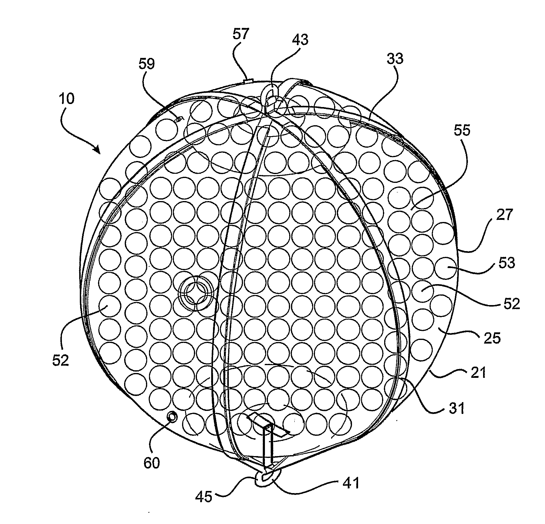
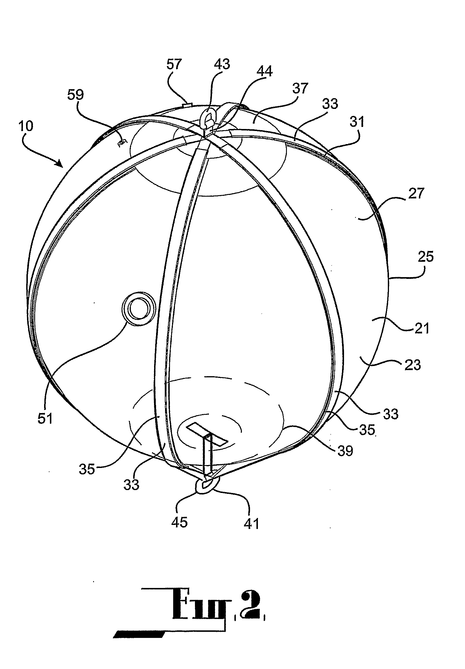
[0091]Referring to FIGS. 1 to 5, the buoyant actuator 10 comprises a body 21 defining a chamber 23 of generally spherical configuration. Specifically, the chamber 23 is defined by a generally spherical wall structure 25 comprising an outer skin 27 formed by a pliant membrane. The outer skin 27 may be constructed of panels 28 of the pliant membrane material bonded together. The pliant membrane comprises a fabric reinforced polymer material such as the commercial product Hypalon® that is widely used for the manufacture of marine buoys and fenders. This material may be glued to itself to form tough waterproof joints as is familiar to persons experienced in this process.

[0092]The wall structure 25 further comprises a reinforcement means 31 extending between upper and lower locations on the body 21. The reinforcement means 31 comprise a plurality of external reinforcing straps 33 configured as hoops 35 extending circumferentially along the surface of the outer skirt 27 and extending thr...

fourth embodiment

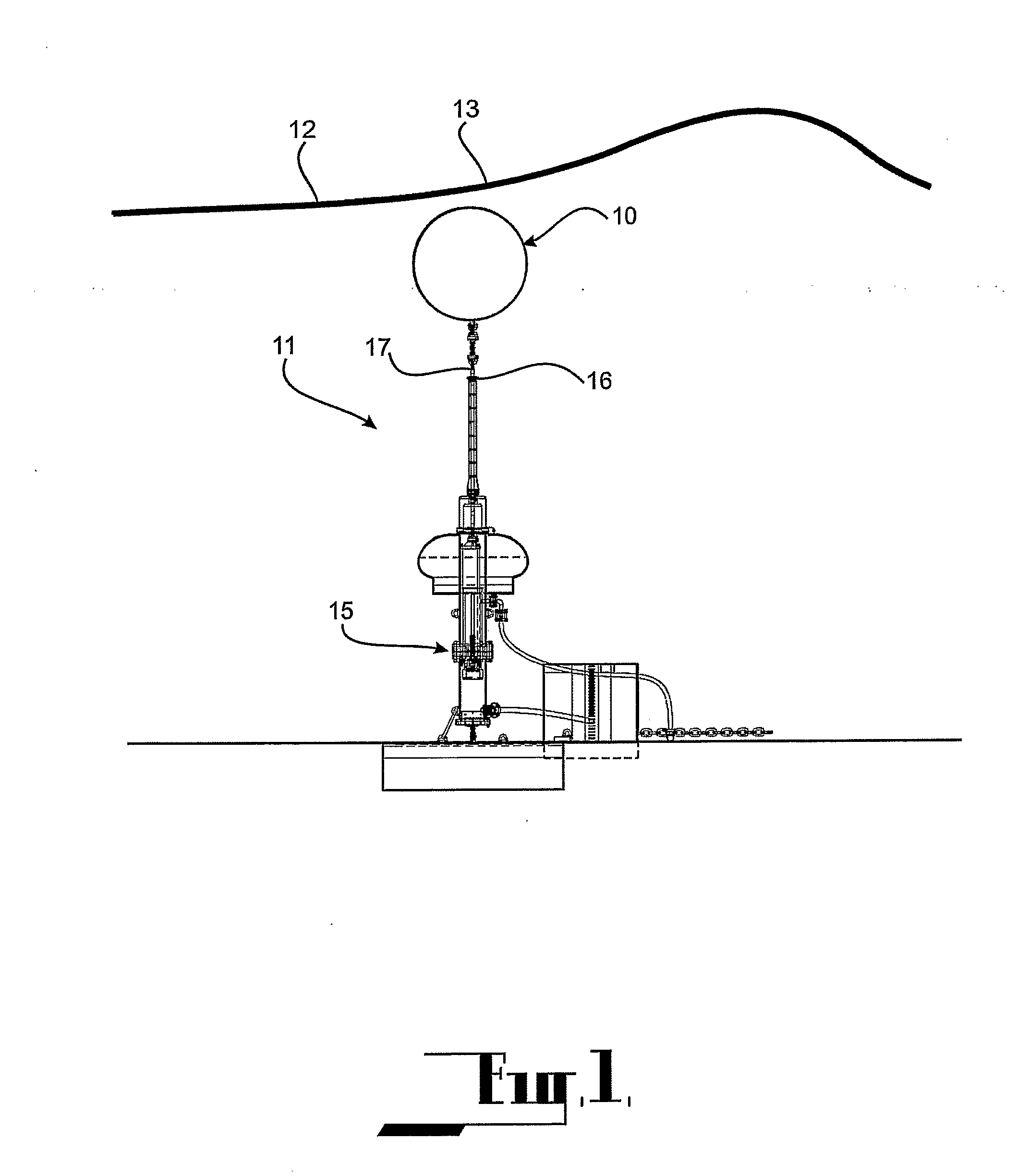
[0123]Referring now to FIGS. 12 to 15, the buoyant actuator 10 has provision to respond to, and recover from, storm conditions without recourse to an external system as do the two previous embodiments.

[0124]In this embodiment, the buoyant actuator 10 comprises a body 101 having a buoyant section 103 below which there is a chamber 105. The chamber 105 is defined by an outer skin 106 comprising cylindrical side wall 107 depending from the buoyant section 103 and a bottom wall 109 which tapers inwardly and downwardly. The side wall 107 and the bottom wall 109 are of pliant material. Specifically, the side wall 107 and the bottom wall 109 are constructed using the same materials and methods employed in relation to the outer skin 27 of the first embodiment.

[0125]The bottom wall 109 incorporates reinforcement means 111 comprising straps 113 attached to, and extending inwardly from, a circumferential reinforcing ring 115 at the outer periphery to a central location 117 at which there is a...

fifth embodiment

[0136]Referring now to FIGS. 16 to 21, the buoyancy actuator 10 is similar to that of the previous embodiment and so like reference numerals are used to identify corresponding parts. In this embodiment, the chamber 105 below the buoyant section 103 is defined by a generally conical downwardly tapering wall structure 131 terminating at reinforced bottom section to which an anchoring point 119 is attached.

[0137]In order to maintain the required degree of buoyancy, supplementary buoyancy is provided to the body. The supplementary buoyancy is provided by a plurality of smaller spherical floats 133 attached to the upper surface of the buoyant section 103.

[0138]This embodiment operates in a similar fashion to the previous embodiment, utilising valves 121, 122.

[0139]It may not be possible to utilise the leaky seam as a one-way valve in this embodiment as the effect of the conical shape on the bending of the skin would make it difficult to apply this technique. Normal one-way valves are th...


PUM


Abstract

A buoyant actuator (10) for use in apparatus (11) for harnessing ocean wave energy and for converting the harnessed energy to high-pressure seawater. The buoyant actuator (10) comprises a body (21) defining a chamber (23) having a pliant outer skin (27). The chamber (23) is adapted to contain matter and a hydrodynamic property of the body (21) is selectively variable by varying the matter within the chamber (23). The variation to the hydrodynamic property may comprise a variation to the buoyancy (either positively or negatively) or a variation to the response area (such as the volume or shape) of the body (21), as well as a combination thereof. The variation to the matter may comprise addition of matter to, or extraction of matter from, the chamber (23). The matter may comprise a solid, liquid or gas, as well as any combination thereof. In the arrangement shown, the matter comprises foam spheres (53). The outer skin (27) is drawn into a taut condition by the outward pressure of the foam spheres (53) inside, causing the actuator to assume its design shape. The volume occupied by the foam spheres (53) is in total still less than the total enclosed volume of the chamber (23) and there are interstitial regions (55) around each sphere (53). The interstitial regions (55) may be filled with fluid to adjust the buoyancy.

Description

[0001]This invention relates to extraction of energy from wave motion, and more particularly to a buoyant actuator responsive to wave motion as well as a method of operating such an actuator. The invention also relates to a wave energy conversion system and to a method of operating such a system.[0002]The invention has been devised particularly, although not necessarily solely, as an actuator for coupling wave motion to a device operable in response to wave motion. A particular application of the actuator according to the invention is in relation to the harnessing ocean wave energy and for converting the harnessed energy to linear motion for driving an energy conversion device such as, for example, a fluid pump or linear electric generator. In such an arrangement, the actuator may be operably connected to the energy conversion device, the actuator being buoyantly suspended within the body of seawater above the device but typically below the water surface. With this arrangement, dyna...

Claims


Application Information

Patent Timeline
IPC IPC(8): F03B13/14B63B43/06B63B43/08B63B22/20
CPCB63B22/00B63B22/04B63B22/20F05B2270/18Y02E10/38F05B2250/241F03B13/1885Y02E10/30
Inventor BURNS, ALAN ROBERT
Owner CETO IP
Why Eureka
Try Eureka