
Method and Apparatus for Providing a Photobioreactor

a photobioreactor and photoreactor technology, applied in the field of microalgae and cyanobacteria, can solve the problems of insufficient biofuel production yield, negative side effects, and ineffective cropping, and achieve the effects of low construction, operation and maintenance costs, and high production rates

Inactive Publication Date: 2010-07-15
MARGALEF PERE
View PDF7 Cites 10 Cited by
  • Summary
  • Abstract
  • Description
  • Claims
  • Application Information

AI Technical Summary

Benefits of technology

[0024]The illustrated embodiments of the invention respond to the specific need for mass, cost-effective microalgae and cyanobacteria biomass production. The illustrated embodiments of the invention are based on a concept which offers the advantages of both raceway and closed tubular photobioreactors, namely the low costs of construction, operation and maintenance for the open raceway technology and the advantageous features of the closed photobioreactors (i.e. high production rates and biological safety). The illustrated embodiments of the invention respond to the specific need for an economically viable mass production of biofuels. The illustrated embodiments of the invention include a closed photobioreactor which can operate in a continuous manner either in an outdoor or indoor environment.
[0027]In another embodiment, the present invention comprises a hydraulic circuit open to atmospheric pressure in which the algal / bacterial culture may be protected from external pollution since the photosynthesis reaction occurs within and along the transparent tubes. As a result, in order to protect the algal / bacterial culture from external pollution, it is only necessary to cover the receiving channels, which surface is an insignificant portion with respect to the total surface of the photobioreactor. In addition, since the system is closed to contamination, it is very straightforward and cost effective to eliminate the oxygen and to feed the nutrients and carbon dioxide into it.
[0029]Because the system is an open hydraulic system (i.e. at atmospheric pressure), moving the algal / bacterial solution throughout the photobioreactor is straightforward and inexpensive. In one embodiment, the fluid moving device induces a difference in the surface level between the sides of the moving device. In addition, the same device may help to eliminate the oxygen from the algal / bacterial solution (i.e. degasification). The fluid moving device may be a rotary direct lift device such as a paddle wheel, noria, scoop wheel, etc. which may or may not incorporate perforated blades to enhance degasification.

Problems solved by technology

However, these traditional crops are not cost effective and the biofuel production yield is not high enough to compete with petroleum and its derivates.
Therefore, the production of biofuels from traditional crops may lead to negative side effects such as intolerable rises in food prices and other global issues.
However, open photobioreactors do not easily sustain the conditions for desired microalgae and cyanobacteria growth because the conditions of the algal culture can vary substantially over time due to water evaporation.
In addition production is affected by contamination with unwanted algae and microorganisms that are deposited on the algal culture.
However, with this technology, the oxygen produced during the photosynthesis, which is toxic to the algae and bacteria, may become an issue and might be hard to eliminate.
Additionally, the cost of installation is around ten times higher than the cost of raceway photobioreactors.
Due to the high costs, closed photobioreactors are not yet economically viable.
Current photobioreactors present important limitations to producing microalgae and cyanobacteria at a large scale.
Whereas some of them require enormous amounts of energy to operate, others present prohibitive construction, installation and maintenance costs.
Today, the bottleneck for the production of massive amounts of microalgae and cyanobacteria is the photobioreactor itself.

Method used


Image

  • Method and Apparatus for Providing a Photobioreactor
  • Method and Apparatus for Providing a Photobioreactor
  • Method and Apparatus for Providing a Photobioreactor

Examples


Embodiment Construction

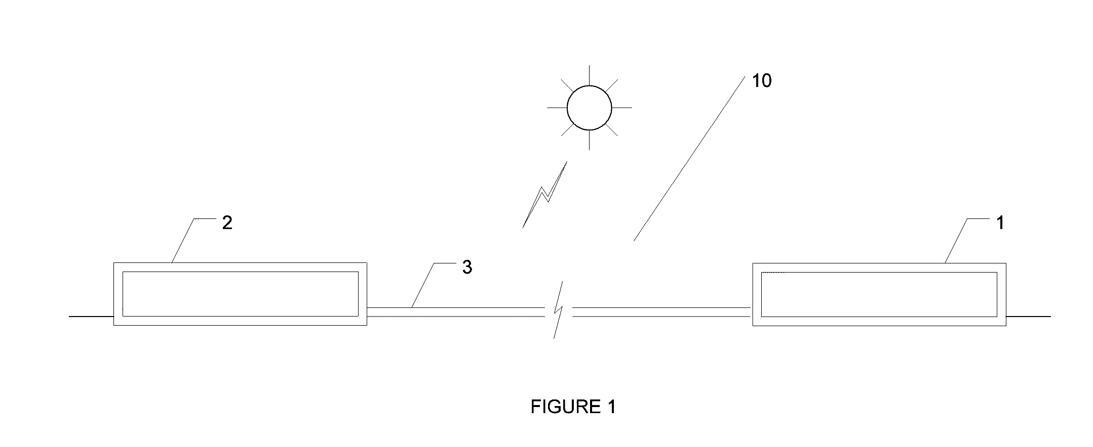
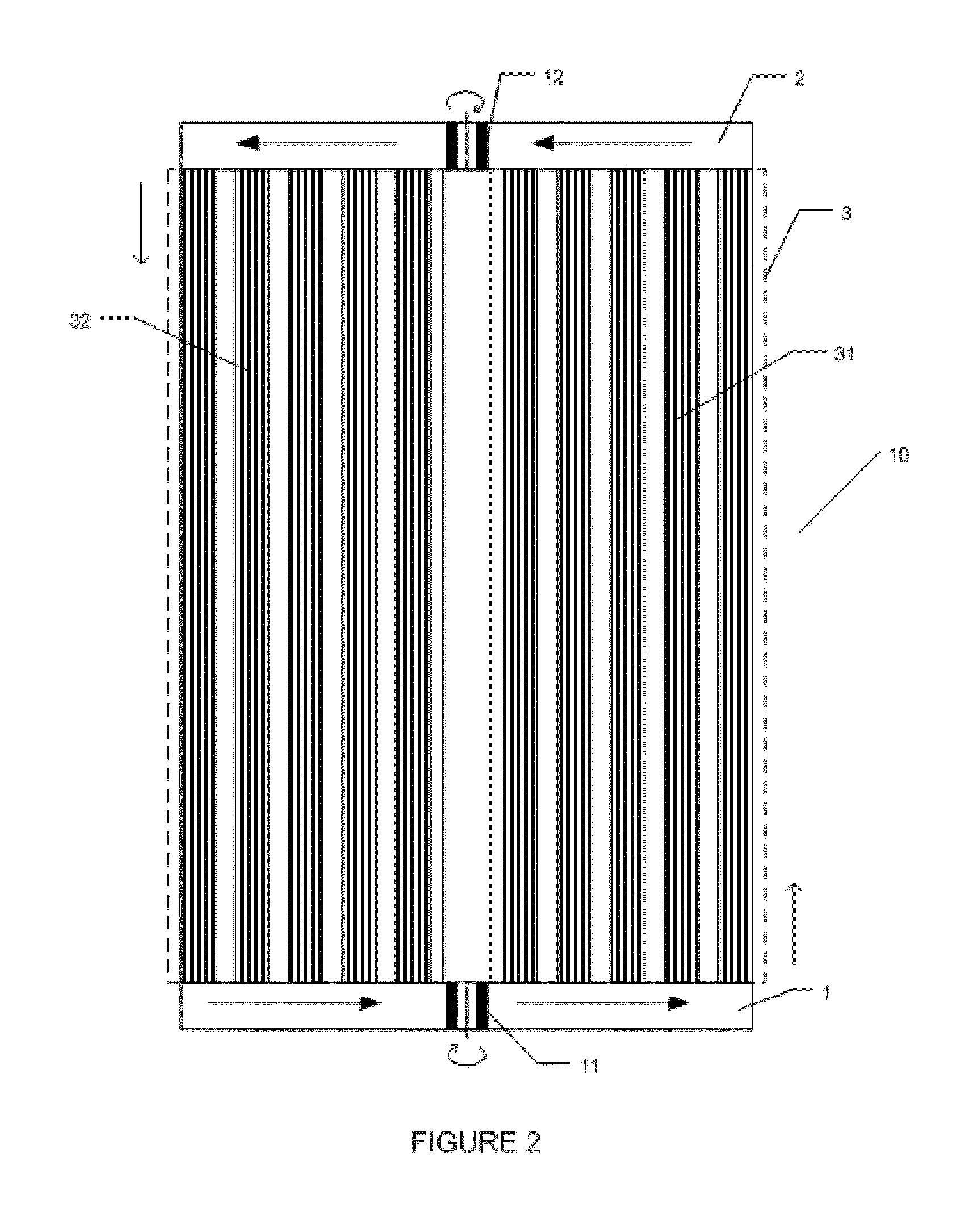
[0041]Turning to FIG. 1, one of the illustrated embodiments of the invention provides for a tubular photobioreactor 10 open to atmospheric pressure which comprises a horizontal tube set 3 disposed between a first receiving channel 1 and a second receiving channel 2 designed for massive algal / bacterial production. An aqueous solution contained within the receiving channels 1, 2 is circulated by a first fluid moving device 11 and a second fluid moving device 21 respectively as best seen in FIGS. 2 and 7.

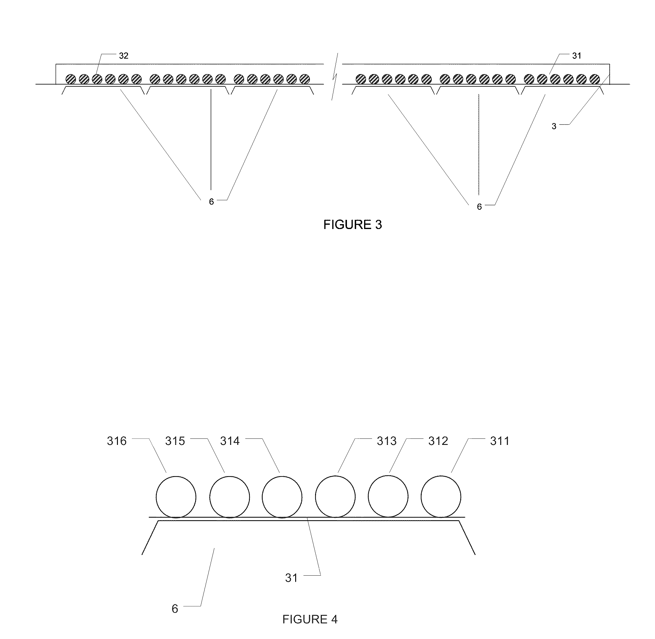
[0042]In one embodiment of the invention, the horizontal tube set 3 of the photobioreactor 10 comprises a plurality of subsets or “ramps”31, 32 of tubes as seen in FIGS. 2, 3 and 7. For definitional purposes, ramps comprising the right-hand hemisphere of the horizontal tube set 3 as seen in FIG. 2 are denoted with reference numeral 31, while ramps comprising the left-hand hemisphere of the horizontal tube set 3 are denoted with reference numeral 32. Each ramp 31, 32 in turn comprises a...


PUM


Abstract

The present invention provides for a photobioreactor for the cultivation of photosynthetic microorganisms and comprises a hydraulic circuit through which an aqueous solution containing culture of at least one type of photosynthetic organism circulates and gets exposed to a light source. The photobioreactor also comprises a means for feeding carbon dioxide into the system, a means for oxygen degasification, and a means for injecting nutrients into the system. The hydraulic circuit is comprised of two open receiving channels at the same relative elevation, a set of transparent or translucent tubes which connect receiving channels to each other, and at least one fluid moving device to move the fluid from the first to the second receiving channels through the tubes. Each receiving channel also comprises a dam which assists in maintaining two different surface levels of the aqueous solution within the upstream and downstream portions of each receiving channel.

Description

BACKGROUND OF THE INVENTION [0001]1. Field of the Invention[0002]The invention relates to the field of microalgae and cyanobacteria, specifically how microalgae and cyanobacteria may be cultivated to produce biofuels, food for humans and animals, organic fertilizers or pharmaceutical products.[0003]2. Description of the Prior Art[0004]Due to the increasing costs of fossil fuels as well as its negative impact for the environment (e.g. climate change) there is a growing interest for the use of biofuels such as biodiesel and bioethanol. So far, these biofuels have been obtained from traditional oleaginous and cellulose rich feedstock. However, these traditional crops are not cost effective and the biofuel production yield is not high enough to compete with petroleum and its derivates. Therefore, the production of biofuels from traditional crops may lead to negative side effects such as intolerable rises in food prices and other global issues.[0005]One of the most promising solutions to...

Claims


Application Information

Patent Timeline
IPC IPC(8): C12N1/20C12N1/12C12M1/00
CPCC12M21/02C12M27/06C12M23/06C12M1/065C12N1/12
Inventor MENA MAS, JACINTO FERNANDO
Owner MARGALEF PERE
Learn More