Heat regeneration for a turbofan, a Velarus Propulsion

a turbofan and propulsion technology, applied in the field of turbofans, can solve the problems of inability to regenerate waste heat, inability to implement invention architecture, and innovative theoretical thermal efficiency, and achieve the effects of improving the longevity of the components, reducing pollution, and reducing the cost of fuel and cos

Inactive Publication Date: 2010-07-22
SACHS HUMBERTO W
View PDF3 Cites 30 Cited by
  • Summary
  • Abstract
  • Description
  • Claims
  • Application Information

AI Technical Summary

Benefits of technology

[0032]k. The supplemental details of the fanblade's root attachment to the rotor and the flame tube design are also options available to the VPx designer, and are here claimed as elements of this invention, facilitating manufacturing and improving the longevity of the components.
[0033]The embodiment of this invention is to deliver an efficient, fu

Problems solved by technology

Its theoretical thermal efficiency is not innovative and it cannot regenerate waste heat, exhausting the combustion gases above 730° K. While GE significantly increased the fan by-pass over previous engines, an obvious optimization, only heat regeneration can

Method used


Image

  • Heat regeneration for a turbofan, a Velarus Propulsion
  • Heat regeneration for a turbofan, a Velarus Propulsion
  • Heat regeneration for a turbofan, a Velarus Propulsion

Examples


Embodiment Construction

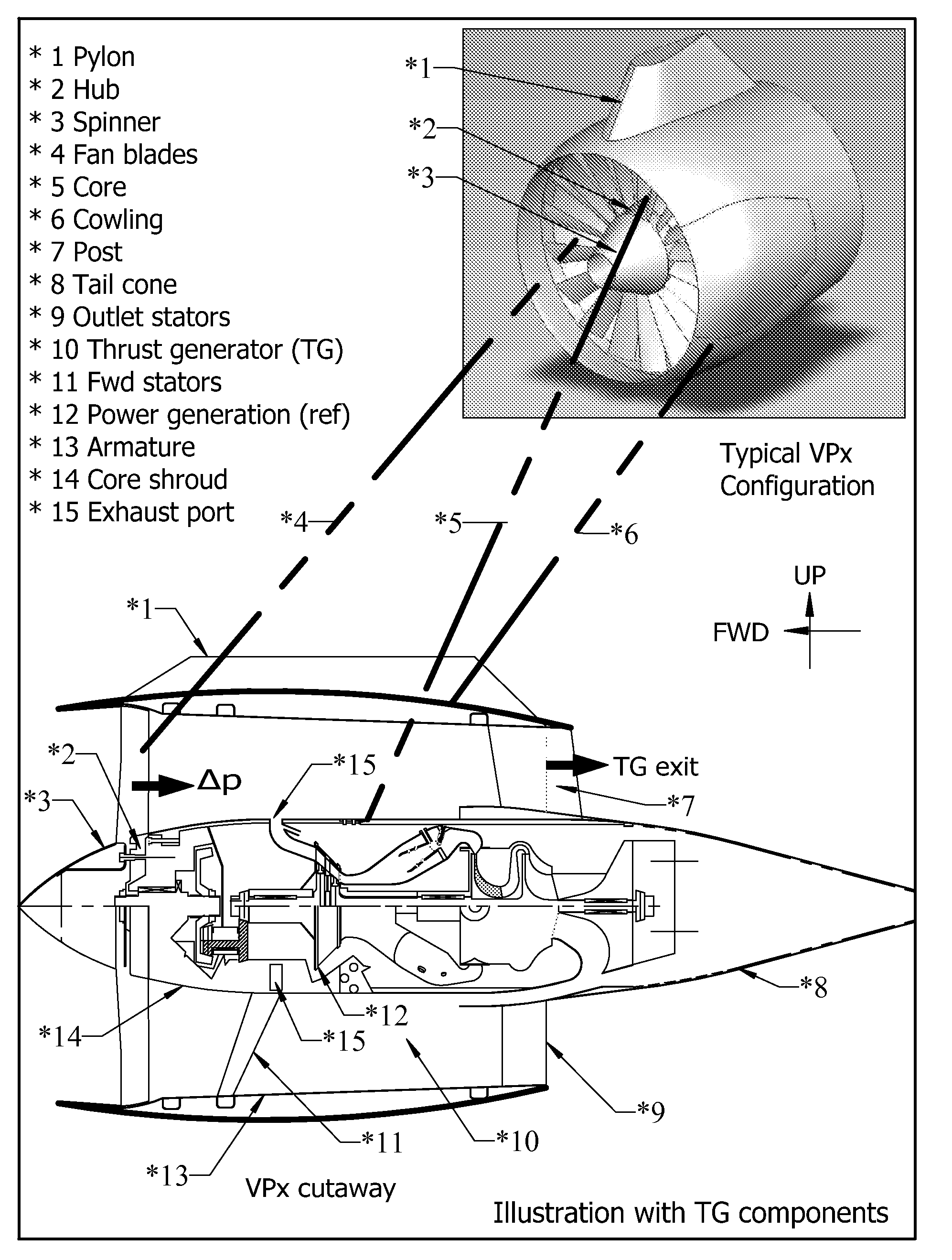
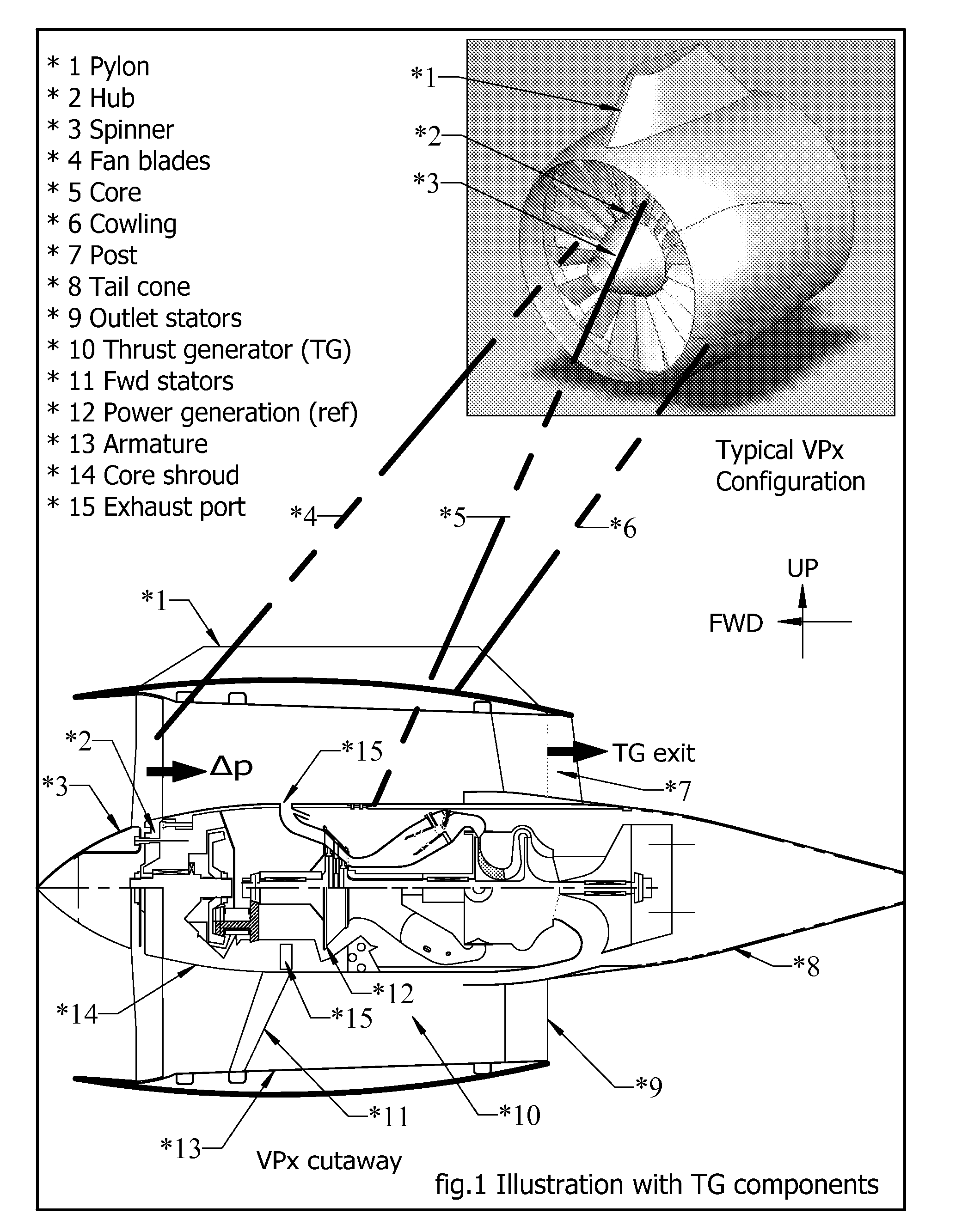
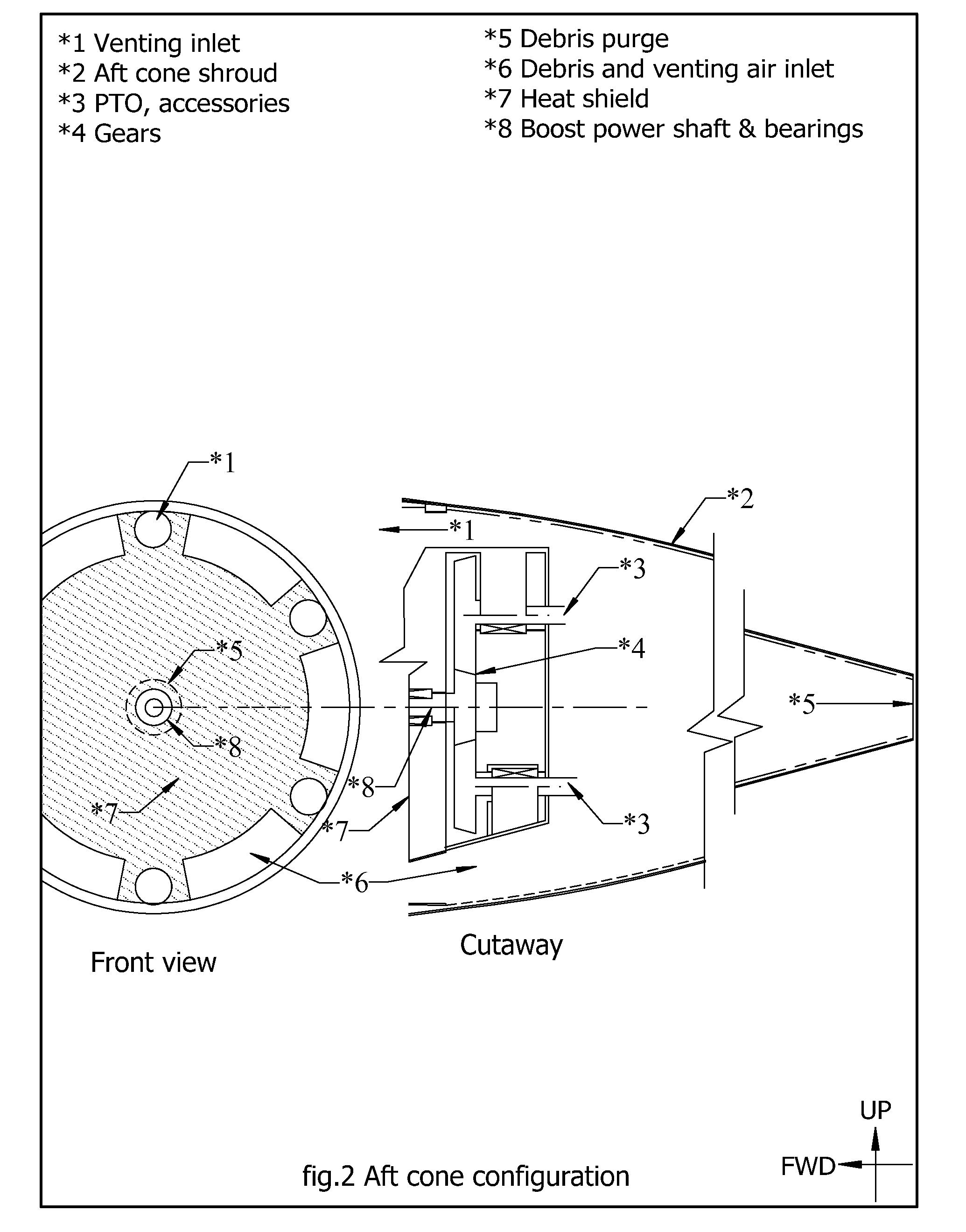
[0034]The specific architecture, configuration and functional details composing the embodiment of this invention allows for the VPx propulsion to be used in new aircraft design or to replace the propulsion units on existing aircraft. The airframe's appropriate design of the cowling inlet duct will make the VPx suitable for subsonic or supersonic flight. The major functional modules of the invention consists of the thrust generator (FIG. 1), the aft cone (FIG. 2) and the power generation modules in the core (FIG. 3) which includes reference to the generic hub. To improve clarity, the illustrations do not include the customary and standard structures consisting of beams, shear webs, cylinders and ribs. The illustrations intend to communicate the invention's essential layout and geometry necessary to implement the heat regeneration concept.

[0035]Referring to the cutaway in FIG. 1, the principal components of the TG includes its fanblades (*4) attached to a hub (*2), the turbine exhaust...


PUM


Abstract

The invention adds details and alternate design supplementing the concept established with my patent application Ser. No. 12/013,431, Aircraft Propulsion System (APS). The APS ultimate fuel economy objectives requires long term design development, and this invention compromises some fuel economy for the expediency of short term implementation of a heat regeneration for turbofans via the re-arrangement of existing components and a few unique items readily designed. While this Velarus Propulsion (VPx) attains only 42% fuel economy, it retains the original APS fundamental architecture implementing heat regeneration for a turbofan engine, as well as the additional benefits of noise and emission abatement. This invention consists of the three APS technologies as follows:
    • a) A novel arrangement of the power generation core features the turbine exhaust entering directly into the thrust chamber, thus providing heat regeneration with an appropriate configuration of the thrust chamber.
    • b) The design of a modified combustor introduces the concept of a supersonic nozzle driving the turbines which allows for greater combustor's chamber temperature while injecting the gases at temperatures acceptable to current turbine blade metallurgy. This feature increases the engine thermal efficiency.
    • c) The hub design allows for two options, a simpler fixed fanblade design or an advanced controllable pitch fan blade, increasing the mission and performance flexibility of a given turbofan size.
In addition, this invention adds functionality to the aft cone, such as debris purge, accessories installation, and thrust reversers free from hot gases.

Description

CROSS-REFERENCE TO RELATED APPLICATIONS[0001]Aircraft Propulsion System, patent pending Ser. No. 12 / 013,431.STATEMENT REGARDING FEDERALLY SPONSORED RESEARCH OR DEVELOPMENT[0002]Not ApplicableREFERENCE TO SEQUENCE LISTING[0003]Not ApplicableCLASSIFICATION OF THE INVENTION[0004]This invention relates generally to aircraft requiring propulsion.Current U.S. Class:244 / 53R and 62Current International Class:IPC8 / B 64 DField of Search:244 / 53R and 62USA Patents searchedNone found comparableBRIEF DESCRIPTION OF THE SEVERAL VIEWS OF THE DRAWING[0005]NALIST OF FIGURES[0006]FIG. 1 Illustration with TG components[0007]FIG. 2 Aft cone configuration[0008]FIG. 3 Core cutaway[0009]FIG. 4 Combustor configuration[0010]FIG. 5 Turbine configuration[0011]FIG. 6 Air inlet manifold configuration[0012]FIG. 7 Exhaust manifold configuration[0013]FIG. 8 Hub optional detail[0014]FIG. 9 Thrust reverser configurationBACKGROUND OF THE INVENTION[0015]While the GEnx (a General Electric turbofan) claims legitimately t...

Claims


Application Information

Patent Timeline
IPC IPC(8): F02C7/10
CPCF02C5/02F02C7/10F23R3/50F23R3/28F23R3/42F02K3/06
Inventor SACHS, HUMBERTO W.
Owner SACHS HUMBERTO W
Why Eureka
Try Eureka