
Cross-linked polyimide membranes

a polyimide membrane and cross-linked technology, applied in the direction of separation processes, ultrafiltration, water/sludge/sewage treatment, etc., can solve the problems of membrane polymer dissolution, lack of membrane stability, and decrease of selectivity

Inactive Publication Date: 2010-07-22
EVONIK FIBERS
View PDF1 Cites 24 Cited by
  • Summary
  • Abstract
  • Description
  • Claims
  • Application Information

AI Technical Summary

Benefits of technology

[0015]The present invention provides a method for the modification of an ultra- or nanofiltration polyimide membrane in order to increase its solvent resistance while maintaining the permeability of the membrane.

Problems solved by technology

The separation process can be disturbed by an unwanted swelling of the membrane (in certain solvents), which can for instance decrease the selectivity and eventually lead to dissolution of the membrane polymer.
During the actual filtration, the lack of membrane stability is often observed as an excessive swelling or ultimately even as the complete dissolution of the polymer in the organic solvents constituting the feed to be treated.
Consequently, membrane selectivities drop and membranes become useless.
In principle, ceramic membranes are resistant in any organic solvent within a certain pH-range and even at elevated temperatures, but they are expensive and often show low or even no fluxes for organics as soon as the pore sizes decrease to the lower NF-range (typically from 400 Da onwards).
Some solvent classes however lead to severe stability problems for these polymers.
Particularly, the group of aprotic solvents such as dimethylformamide (DMF), N-methylpyrrolidinone (NMP), dimethylacetamide (DMAC), tetrahydrofuran (THF), y-butyrolacton (GBL), dimethylsulphoxide (DMSO) and chlorinated solvents, remains a problematic solvent class.
Highly stable cross-linked elastomers, such as polydimethylsiloxane, are too hydrophobic to be applied successfully in these solvents.
Even though performing very well in gas separations, their potential for SRNF in organic solvents is restricted due to too low affinity for the permeating hydrocarbon.
These methods are usually quite complicated and demand a lot of organic synthesis effort.
However, these membranes are limited to the UF range and have a low efficiency in operation.
. . ) treatments either breakdown polymer chains (see example 6), thus destroying the mechanical stability of the membranes and / or increasing the pore sizes of the membrane, or modify the membrane surface to such an extend that affinity for the permeating compounds and hence their permeation has drastically decreased.

Method used


Image

  • Cross-linked polyimide membranes
  • Cross-linked polyimide membranes
  • Cross-linked polyimide membranes

Examples


example 1

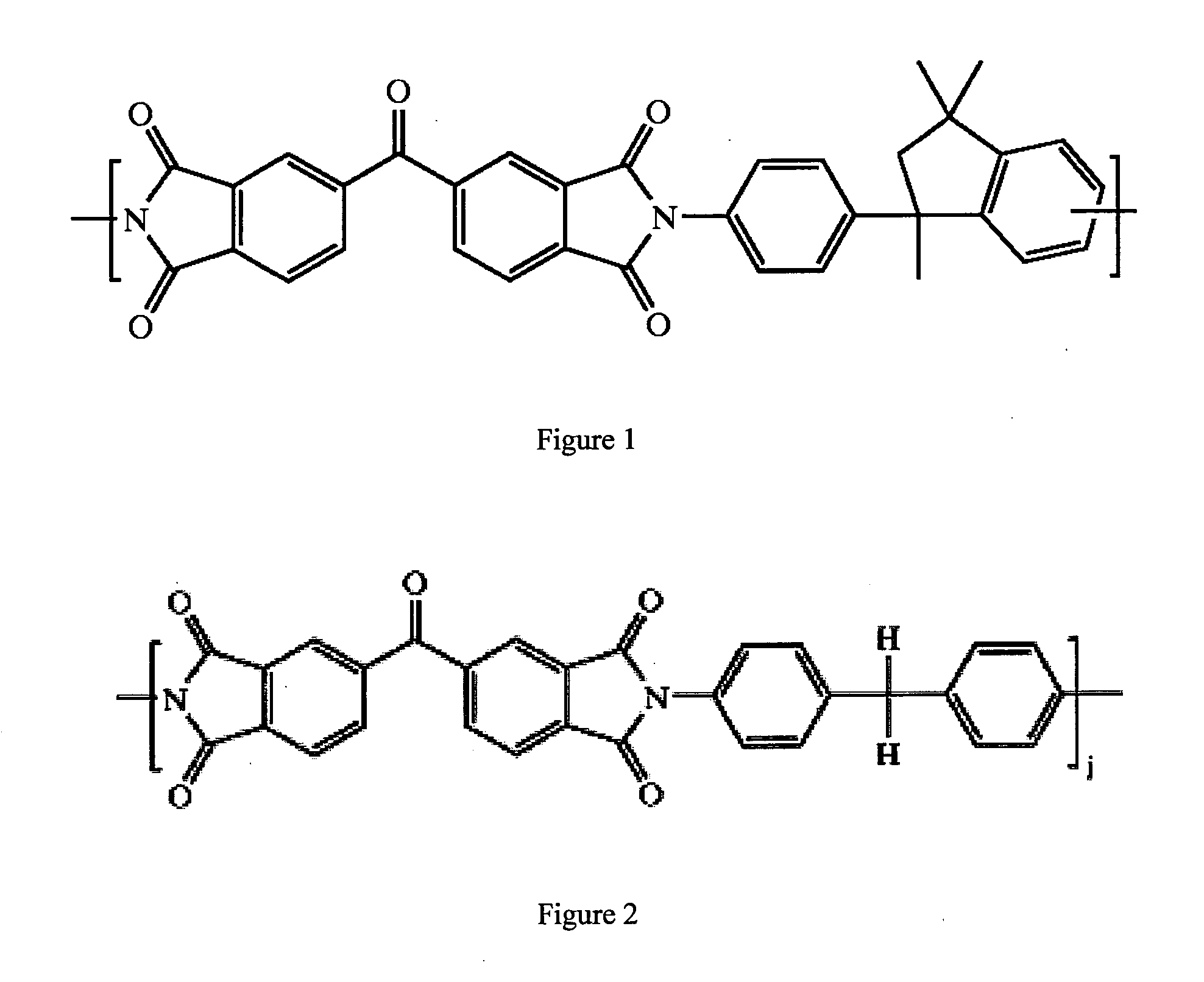
[0028]An 18 wt % solution of matrimid 9725 polyimide (Huntsman) was made in NMP and THF (ratio 2:1) by stirring overnight. The polymer solution was cast on a polypropylene non-woven support by an automated casting device set at a gap of 250 μm. The resulting film was immersed in a de-ionized water bath after 30 s of evaporation.

[0029]Parts of the resulting membrane were immersed in a solution of p-xylenediamine in methanol for cross-linking. After 5, 60 and 120 minutes, the membrane slabs were removed and rinsed with methanol to remove all reactant. The membranes were then immersed in IPA until use for immersion experiments. Parts of the cross-linked membranes were immersed in DMSO for several days, after which they were again immersed in IPA until they were used for filtrations.

[0030]Filtrations were carried out in a stainless steel dead-end filtration cell, pressurized with nitrogen gas to 6 bars, with a solution of bengal rose in WA (35 μM) on top of the cross-linked membranes, b...

example 2

[0031]Membranes were prepared and cross-linked as in example 1. Cross-linked membrane slabs were immersed in NMP for several days. Uncross-linked membrane slabs were immersed in NMP in which they dissolved after some hours. Filtrations were carried out as in example 1. The results show that 60 minutes or longer cross-linked membranes retain their excellent performance in WA after immersion in NMP.

after immersionbefore immersionin NMPwt %Cross-linkingpermeancerejectionpermeanceRejectionPI(minutes)l / m2 bar h%l / m2 bar h%1852.2292.91.0898.3(high occurrenceof defects)18600.8597.12.0598.2181200.7596.41.7997.2The first result proves the non-obvious success of a chemical modification to a membrane.

example 3

[0032]Membranes were prepared and cross-linked as in example 1, but an NMP-exchanged clear solution (NMP-CS) was added as an extra component to the polymer casting solution. This NMP-CS emulsifies the polymer dope before casting, which was further treated as in example 1. During this modified phase-inversion process called ‘solidification of emulsified polymer dope by phase inversion’ or ‘SEPPI’ (Gevers, 2006), a membrane is created with uniform spherical pores that is more resistant to compaction at high pressures. Membranes were further treated as in example 1. Cross-linked membrane slabs were immersed in DMF. Uncross-linked slabs that were immersed in DMF dissolved completely after some hours. Filtrations were carried out as in example 1.

[0033]Results show that a cross-linking treatment of 60 minutes or more is sufficient to create membranes stable in DMF, which retain their excellent performance in IPA after immersion in DMF.

before immersionafter immersionin DMFin DMFwt %Cross-l...


PUM

PropertyMeasurementUnit
molecular weightaaaaaaaaaa

Abstract

The present invention provides a method for improving the performance of polyimide membranes as used in solvent-resistant nanofiltration. More specifically the method of the present invention allows to improve the solvent stability of the polyimide membranes to solvents or solvent mixtures that would dissolve polyimide under the conditions applied during the filtration, such as dimethylforrnamide (DMF), N-methylpyrrolidinone (NMP), dimethylacetamide (DMAC), tetrahydrofuran (THF), y-butyrolacton (GBL), dimethylsulphoxide (DMSO) and chlorinated solvents.

Description

FIELD OF THE INVENTION[0001]The present invention relates to improving the performance of polyimide membranes as used in solvent-resistant nanofiltration, and more specifically to extending the solvent stability of the polyimide membranes to solvents or solvent mixtures that would dissolve polyimide under the conditions applied during filtration.BACKGROUND OF THE INVENTION[0002]Nanofiltration is a pressure-driven separation process. It involves a process of separating two or more components over a membrane by means of a pressure gradient, generated by applying pressure to the feed side of the membrane, either a gas pressure or a mechanical pressure. The pressure-driven membrane processes can be divided into 4 groups, depending on the applied pressure, for which typical values are given in table 1 (Mulder, 1996). When referring to solvent applications in specific, the term solvent resistant nanofiltration (SRNF) also includes reverse osmosis and the high pressure end of ultrafiltrati...

Claims


Application Information

Patent Timeline
Patent Type & Authority Applications(United States)
IPC IPC(8): B01D61/14C08G73/10B01D61/18
CPCB01D53/228B01D61/027B01D67/0088B01D67/0093B01D2325/34B01D71/64B01D2323/30B01D2325/30B01D67/0095B01D2325/341
Inventor VANDEZANDE, PIETERVANHERCK, KATRIENVANKELECOM, IVO
Owner EVONIK FIBERS
Learn More