

Image-forming apparatus and cartridge
- Summary
- Abstract
- Description
- Claims
- Application Information
AI Technical Summary
Benefits of technology
Problems solved by technology
Method used
Image

Examples
example 1
Charge-Generating Material-Producing Example 1
(Preparation of CG1)
[0741]Sixty grams of α-type oxytitanium phthalocyanine was slowly added to 1.5 kg of concentrated sulfuric acid at 5° C. or less to prepare an oxytitanium phthalocyanine solution in concentrated sulfuric acid. The resulting oxytitanium phthalocyanine solution in concentrated sulfuric acid was placed into 15 kg of iced-water at 5° C. or less to precipitate oxytitanium phthalocyanine. The precipitated oxytitanium phthalocyanine was collected by filtration and thoroughly washed with water until the water used for the washing had a pH of neutral to give aqueous paste of oxytitanium phthalocyanine. The solid content of this aqueous paste was 12 mass %. One kilogram of n-octane was added to the aqueous paste, and the resulting mixture was subjected to milling with glass beads having a diameter of 1 mm for 10 hours for crystal-form transformation to give oxytitanium phthalocyanine crystals for being used as the charge-genera...
example 26
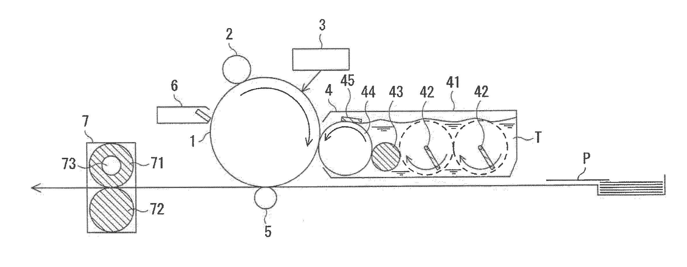
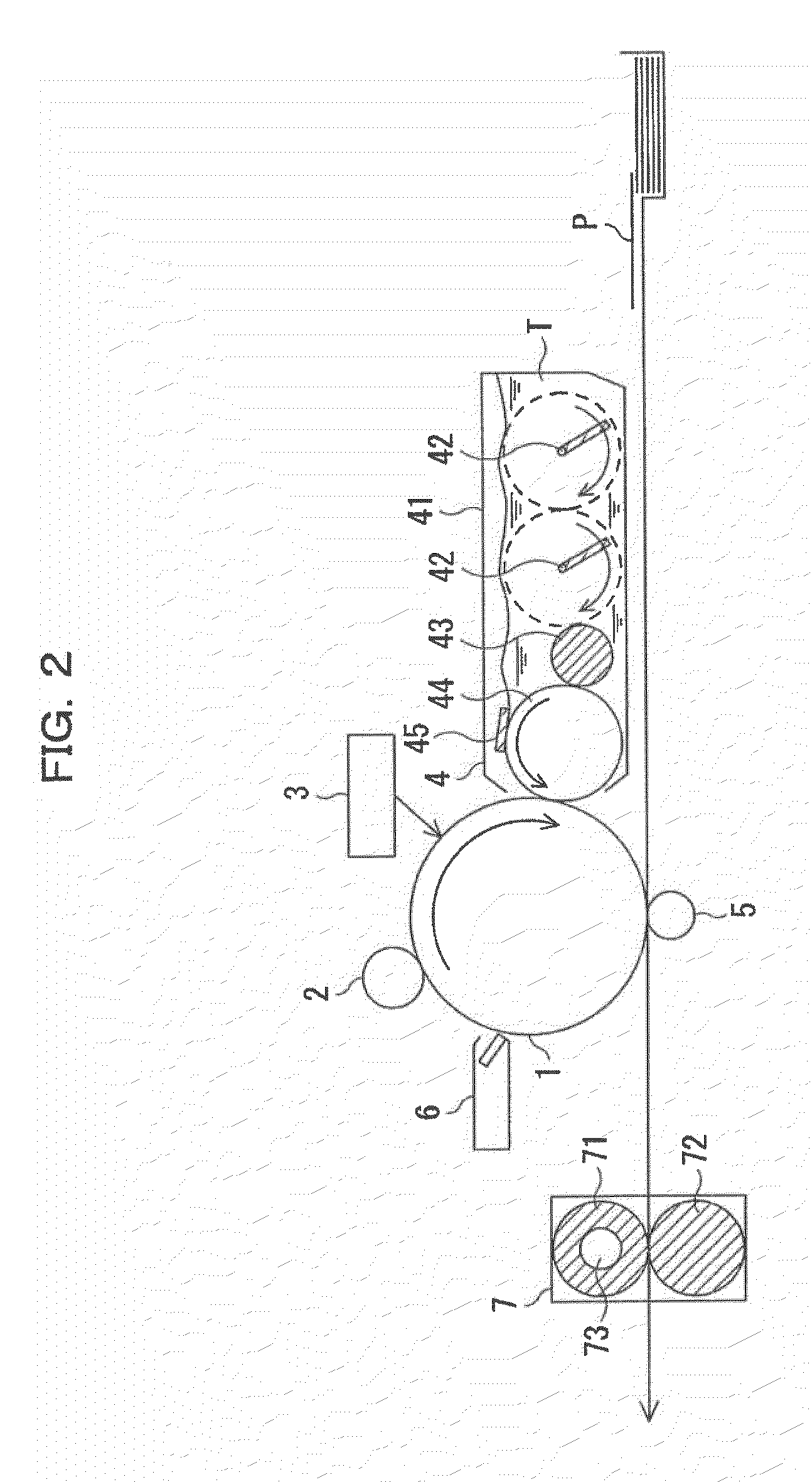
[0865]The photoreceptor 5 produced in above was mounted on a black drum cartridge of Microline Pro 9800PS-E (modified) manufactured by Oki Data Corp., and the cartridge was loaded in the printer. The specifications of the Microline Pro 9800PS-E (modified) were as follows. The “ppm” in the following specifications means the number of sheets printed per minute.
[0866]Printing system: four-stage tandem
[0867]Number of printing sheets: 36 ppm (color), 40 ppm (monochrome)
[0868]Number of pixels: 1200 dpi
[0869]Charging system: contact-type roller charging
[0870]Exposure system: LED exposure
[0871]Erase light: none
[0872]The toner produced in “Development toner-producing example 10” having an average sphericity of 0.963, a volume-average particle diameter of 7.05 μm, and a Dv / Dn of 1.14 or the toner produced in “Development toner-producing example 11” having an average sphericity of 0.981 was used.
[0873]A pattern having a boldface character in white on the upper area and a halftone portion from ...
PUM
 Abstract
Description
Claims
Application Information